System and method for treating converter flue gas

A converter flue gas and treatment system technology, which is applied in the direction of manufacturing converters, improving process efficiency, improving energy efficiency, etc., can solve the problem that thermal energy water-cooled sensible heat is not effectively recycled, electrostatic precipitator scaling, and corrosion cannot be completely Solve and affect the waste heat recovery of flue gas and other problems, and achieve the effect of preventing unsafe factors, obvious dust removal effect, and alleviating dust removal pressure

Inactive Publication Date: 2013-01-30
北京五一环保科技股份有限公司
View PDF6 Cites 20 Cited by
  • Summary
  • Abstract
  • Description
  • Claims
  • Application Information

AI Technical Summary

Problems solved by technology

[0005] The wet purification and dust removal system has a long history of evolution and is constantly improving. Now the fourth generation wet process is more advanced. It has many advantages, but the main disadvantage is that the entire flue gas is treated with water, and the water consumption is large. The consumption of water resources is large; the combination of spray washing and annular seam washing increases the height of the tower body, shortens the distance of the flue exit, and affects the recovery of waste heat from the flue gas. wasted
The main disadvantage is that there is a lot of one-time investment, often in the hundreds of millions of yuan; due to the high degree of automation and high requirements for operation and maintenance, it is not suitable for many small and medium-sized converters with low control levels; especially for electrostatic precipitator fouling, The corrosion problem has not been completely solved; and the sensible heat of a large amount of thermal energy in the flue gas has not been effectively recycled

Method used


Image

  • System and method for treating converter flue gas

Examples


Embodiment Construction

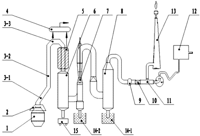
[0017] see figure 1 , a converter flue gas treatment system, comprising a converter 1, including a sequentially connected furnace mouth nitrogen injection sealing smoke hood 2, segmented gasification cooling flue 3-1, 3-2, 3-3, high-temperature heat pipe steam generation 5, spray evaporative cooler 6, long-necked adjustable throat Venturi tube 7, impeller type composite dehydrator 8, fan 9, gas automatic continuous detection device 10, three-way switching valve 11; three-way switching valve 11 and gas The cabinet 12 is connected; or the three-way switching valve 11 communicates with the chimney 13. Fume hood 2 is reported in detail in CN202492534U disclosed converter mouth and fume hood soft sealing device.

[0018] The fume hood 2 , the sectional gasification cooling flue 3 - 1 , 3 - 2 , 3 - 3 , and the high temperature heat pipe steam generator 5 are respectively connected with the steam drum 4 . The spray evaporative cooler 6 communicates with the dry ash collection devi...


PUM


Abstract

The invention relates to an environmental-friendly device of an iron and steel enterprise and a dust removal method, that is to say, a system and a method for treating converter flue gas. The system comprises a furnace mouth nitrogen injection sealing petticoat pipe, a segmental evaporation cooling flue, a high-temperature heat pipe steam generator, a spray evaporation cooler, a long neck adjustable throat venturi tube, an impeller type composite dehydrator, a fan, an automatic continuous coal gas detector and a three-way switching valve, which are connected in sequence, wherein the three-way switching valve is connected with a gas chamber; or the three-way switching valve is communicated with a chimney. The method comprises the following steps of: forming a soft sealing screen between a furnace mouth and a petticoat pipe, after segmentally vaporizing and cooling the flue gas, and cooling in a high-temperature heat pipe; after carrying out spray evaporation, cooling and rough dust removal through a dry method, carrying out fine dust removal and cooling by a venturi tube through a wet method, dehydrating the flue gas, and entering into a coal gas recycling stage lastly. According to the invention, the wet method and the dry method are combined, waste heat recovery, coal gas recovery, sewage treatment and dust removal can be planned in a flue gas treatment and utilization system as a whole and the combination action of the device is fully exerted.

Description

[0001] [0002] technical field [0003] The invention relates to an environmental protection equipment and a dust removal method for iron and steel enterprises, that is, a converter flue gas treatment system and treatment method. Background technique [0004] In the prior art, iron and steel enterprises will produce a large amount of flue gas during smelting. The flue gas contains a large amount of harmful gases such as dust and sulfur. At the same time, it will also produce usable substances such as waste heat and coal gas. A major topic of energy conservation and emission reduction in the industry. At present, according to the different methods of flue gas cooling and dust collection, it is mainly divided into: wet purification and dust removal system, dry purification and dust removal system. [0005] The wet purification and dust removal system has a long history of evolution and is constantly improving. Now the fourth generation wet process is more advanced. It has man...

Claims


Application Information

Patent Timeline
Patent Type & Authority Applications(China)
IPC IPC(8): C21C5/40
CPCY02P10/25
Inventor 吴奕
Owner 北京五一环保科技股份有限公司
Why Eureka
Try Eureka