
Bimetal centrifugal composite brake drum and preparation method thereof

A centrifugal composite and brake drum technology, applied in the field of automobile manufacturing, can solve the problems of inability to use high-strength medium-carbon low-alloy steel, complex composite brake drum technology, increased brake drum weight, etc., and achieves high production efficiency and weight. Lightening, high material utilization effect

Active Publication Date: 2022-03-01
山西汤荣机械制造股份有限公司
View PDF17 Cites 2 Cited by
  • Summary
  • Abstract
  • Description
  • Claims
  • Application Information

AI Technical Summary

Problems solved by technology

[0007] However, the process of producing the composite brake drum by the above-mentioned method is complicated, and steel plates need to be processed into the upper flange part and the lower barrel part of the welded steel ring composite brake drum respectively, and the upper flange part and the lower barrel part are welded into one body Obtain the fine-spinning blank of the outer steel shell of the composite brake drum, and roll the fine-spinning blank of the outer steel shell of the composite brake drum to form the outer steel shell of the composite brake drum
Since the outer steel shell needs to be rotary roll formed, only mild steel with good plasticity can be used instead of high-strength medium-carbon low-alloy steel
The melting point of low-carbon steel is significantly higher than that of medium-carbon low-alloy steel. Therefore, in the subsequent centrifugal casting of the inner layer of gray cast iron, in order to ensure that the inner layer of gray cast iron and the outer layer of low-carbon steel shell are firmly bonded, the outer layer of low-carbon steel shell is required High temperature preheating treatment, inconvenient operation and high energy consumption
In addition, low-carbon steel has low strength and is easy to deform during casting and use. In order to prevent deformation, the thickness of the steel shell needs to be increased, resulting in an increase in the weight of the brake drum.

Method used


Image

  • Bimetal centrifugal composite brake drum and preparation method thereof
  • Bimetal centrifugal composite brake drum and preparation method thereof
  • Bimetal centrifugal composite brake drum and preparation method thereof

Examples


Embodiment 1

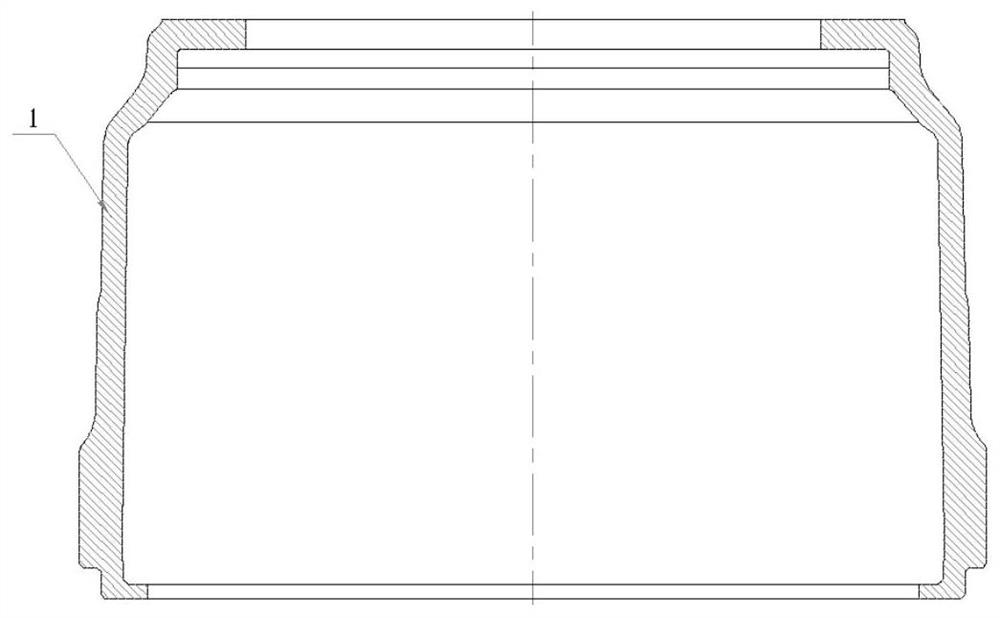
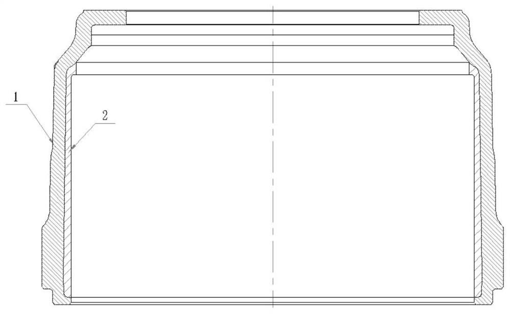
[0027] A bimetallic centrifugal composite brake drum and a preparation method thereof, and the outer layer is made of high-strength carbon low alloy steel, first use centrifugal casting methods to produce medium carbon low alloy steel steel cylinders, and use die forging into composite brakes The tumpet steel shell 1 is then poured on the centrifuge, and the bimetallic centrifugation is obtained, and the specific preparation process step is as follows:

[0028] 1 First in the medium-frequency induction electric furnace, the carbon low alloy steel is melted, and the chemical composition and mass fraction of the medium carbon low alloy steel are controlled at: 0.31% C, 0.37% Si, 0.55% Mn, 0.51% Cr, 0.08% Ti, 0.02% N, 0.003% B, 0.095% Al, 0.0022% Mg, 0.051% Ca, 0.027% CE, 0.023% S, 0.031% p, margin Fe; steel water added 0.08% waste aluminum wire deoxidation, temperature When the 1612 ° C is released; the steel water is allowed to stand, after the slag, the temperature is 1503 ° C, th...

Embodiment 2

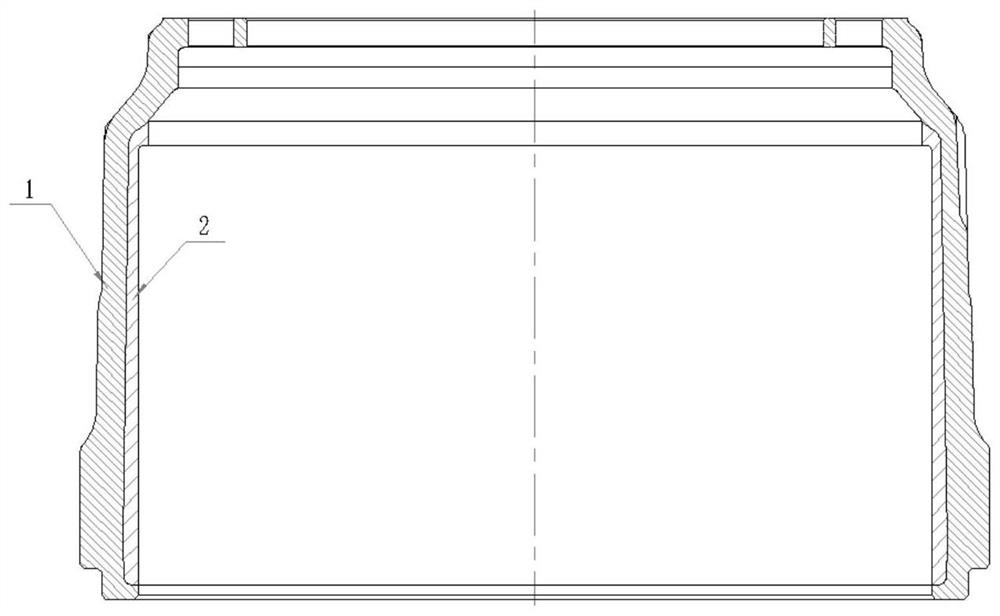
[0033] A bimetallic centrifugal composite brake drum and a preparation method thereof, and the outer layer is made of high-strength carbon low alloy steel, first use centrifugal casting methods to produce medium carbon low alloy steel steel cylinders, and use die forging into composite brakes The tumpet steel shell 1 is then poured on the centrifuge, and the bimetallic centrifugation is obtained, and the specific preparation process step is as follows:

[0034] 1 First in the molten induction electric furnace, the carbon low alloy steel is melted, and the chemical composition and mass fraction of the medium carbon low alloy steel are controlled at: 0.43% C, 0.19% Si, 0.77% Mn, 0.36% Cr, 0.15% Ti, 0.06% N, 0.006% B, 0.068% Al, 0.0035% mg, 0.035% Ca, 0.048% CE, 0.021% S, 0.029% P, margin Fe; steel water added 0.12% waste aluminum wire deoxidation, temperature When the 1627 ° C is released; the steel water is allowed to stand, after the slag, the temperature is 1520 ° C, the casting ...

Embodiment 3

[0039] A bimetallic centrifugal composite brake drum and a preparation method thereof, and the outer layer is made of high-strength carbon low alloy steel, first use centrifugal casting methods to produce medium carbon low alloy steel steel cylinders, and use die forging into composite brakes The tumpet steel shell 1 is then poured on the centrifuge, and the bimetallic centrifugation is obtained, and the specific preparation process step is as follows:

[0040] 1 First in the molten induction electric furnace, the carbon low alloy steel is melted, and the chemical composition and mass fraction of the medium carbon low alloy steel are controlled at: 0.38% C, 0.26% Si, 0.59% Mn, 0.47% Cr, 0.12% Ti, 0.05% N, 0.005% B, 0.085% Al, 0.0027% mg, 0.041% Ca, 0.036% CE, 0.028% S, 0.030% p, margin Fe; steel water added 0.10% waste aluminum wire deoxidation, temperature When the 1623 ° C is released; the steel water is allowed to stand, after the slag, the temperature is 1514 ° C, the casting ...


PUM

PropertyMeasurementUnit
thicknessaaaaaaaaaa
yield strengthaaaaaaaaaa
thicknessaaaaaaaaaa

Abstract

The double-metal centrifugal composite brake drum is characterized in that an outer layer is made of high-strength medium-carbon low-alloy steel, firstly, a medium-carbon low-alloy steel cylinder is manufactured through a centrifugal casting method, a composite brake drum outer-layer steel shell is machined through die forging, and then the outer-layer steel shell is fixed to a centrifugal machine; the inner layer and the outer layer are in good metallurgical bonding, the outer layer is high in strength and good in toughness, the inner layer is high in strength and good in wear resistance and heat resistance, the phenomena of roller breakage and cracking do not occur in the using process, the service life is prolonged by more than two times compared with a single gray cast iron brake drum, and the service life is prolonged by more than two times. The method has good economic and social benefits in popularization and application.

Description

Technical field [0001] The present invention discloses a brake drum and a preparation method thereof, and more particularly to a bimetallic centrifugal composite brake drum and a preparation method thereof, belonging to the automotive manufacturing technology. Background technique [0002] High-performance automotive brake drums must be both good wear resistance, but also have good antipyretic fatigue, but also guarantees that there is no hard white light (avoiding braking and sorghum), and it has high cost performance. However, these performance requirements are often mutually restriction, so seeking to obtain the best comprehensive performance component design ideas and corresponding process routes, so that the life of the brake drum has increased significantly, which has caused domestic and foreign auto parts production and use departments. extensive attention. [0003] The basic requirements of the automobile brake drum: 1) Boots a strong mechanical impact during brakes, requ...

Claims


Application Information

Patent Timeline
Patent Type & Authority Applications(China)
IPC IPC(8): C22C38/32C22C38/28C22C38/06C22C38/04B22D13/06B22D19/16C22C37/06C22C37/10
CPCC22C38/32C22C38/28C22C38/06C22C38/04C22C38/005C22C38/001C22C38/002C22C37/10C22C37/06B22D13/06B22D19/16Y02P10/20
Inventor 曹全青马胜强靳宏斌王晓妍刘海洋符寒光
Owner 山西汤荣机械制造股份有限公司
Learn More