Medical wound surface nursing medicine applying device
A wound surface and medicine board technology, applied in the field of medical wound care medicine application devices, can solve the problems of time-consuming, laborious, uneven application, etc., and achieve the effects of large spraying range, improved work efficiency, and high work efficiency.
- Summary
- Abstract
- Description
- Claims
- Application Information
AI Technical Summary
Problems solved by technology
Method used
Image
Examples
Embodiment 1
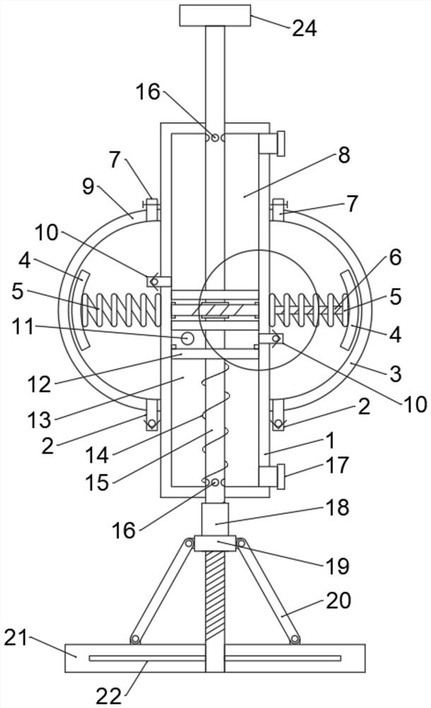
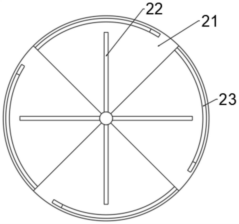
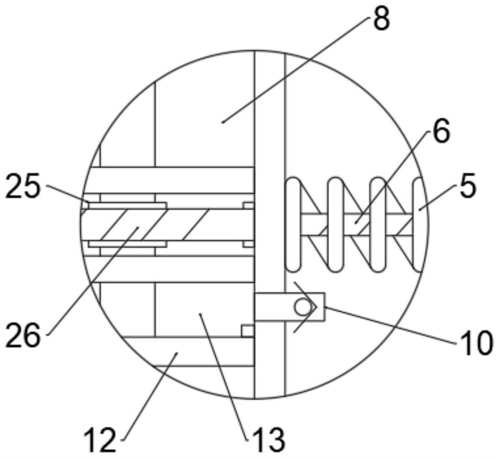
[0038] The embodiment of the present invention provides a medical device for wound care, such as Figure 1-3 shown, including:
[0039]The medicine applicating unit comprises a mounting shaft 15, a medicine spreading plate 21 and an adjustment mechanism. One end of the mounting shaft 15 is circumferentially equipped with a plurality of medicine spreading plates 21. In this embodiment, the medicine spreading plate 21 is preferably fan-shaped, and the mounting shaft 15. A plurality of support rods 22 are fixed at intervals in the upper circumferential direction. The number of support rods 22 is equal to the number of medicine applicator boards 21 and corresponds to each other. Each support rod 22 is movably inserted into the corresponding medicine spread board 21 respectively. It is connected between the installation shaft 15 and a plurality of applicator plates 21, and is used to synchronously adjust the distance between the plurality of applicator plates 21 and the installatio...
Embodiment 2
[0047] This embodiment is on the basis of embodiment 1, as Figure 4-6 As shown, the spraying unit also includes a speed regulating assembly 27, and the speed regulating assembly 27 includes a sliding sleeve 29, a magnet 30, an iron ball 31 and a conical tube 28, and the powder passage in the installation shaft 15 is close to the nozzle 24 One end of the tapered tube 28 is provided with a tapered tube 28, and the diameter of one end of the tapered tube 28 close to the nozzle is smaller than the other end. The outer sliding sleeve of the installation shaft 15 is provided with a sliding sleeve 29, and a magnet 30 is fixedly installed on the sliding sleeve 29. The powder channel The iron ball 31 is placed inside, and the iron ball 31 is magnetically matched with the magnet 30. The suction force of the magnet 30 to the iron ball 31 is greater than the force of the air flow. By moving the sliding sleeve 29, the sliding sleeve 29 drives the iron ball 31 to move, and the iron ball 31 ...
Embodiment 3
[0050] This embodiment is on the basis of embodiment 2, as Figure 7-8 As shown, the powder chamber 8 is provided with a stirring assembly, the stirring assembly includes an elastic stirring piece 34 and an installation net 35, and a plurality of elastic stirring pieces 34 are mounted on the installation shaft 15 at circumferential intervals, and the elastic stirring piece 34 One end is fixedly connected to the installation shaft 15, and the other end is in a free state. In this embodiment, the elastic stirrer 34 is a first arc-shaped rod and a second arc-shaped rod. One end of the first arc-shaped rod is fixed to the installation shaft 15, and the other end In a free state, it protrudes toward the outside of the installation shaft 15. The second arc-shaped rod is fixed on the first arc-shaped rod and protrudes toward the inside of the installation shaft 15. The installation shaft 15 is sleeved with a spring that is in contact with the other end of the elastic stirrer 34. Inst...
PUM
 Abstract
Description
Claims
Application Information
 - R&D
- Intellectual Property
- Life Sciences
- Materials
- Tech Scout
- Unparalleled Data Quality
- Higher Quality Content
- 60% Fewer Hallucinations
Browse by: Latest US Patents, China's latest patents, Technical Efficacy Thesaurus, Application Domain, Technology Topic, Popular Technical Reports.
© 2025 PatSnap. All rights reserved.Legal|Privacy policy|Modern Slavery Act Transparency Statement|Sitemap|About US| Contact US: help@patsnap.com


