Engine inlet air cooling method

An air cooling and engine technology, applied in the field of aerospace power, can solve the problems of long evaporation distance, complex heat exchanger structure, large air flow loss, etc., to reduce flow loss and manufacturing difficulty, improve air pre-cooling efficiency, The effect of increasing the droplet evaporation rate

Pending Publication Date: 2022-03-08
中国空气动力研究与发展中心空天技术研究所
View PDF0 Cites 0 Cited by
  • Summary
  • Abstract
  • Description
  • Claims
  • Application Information

AI Technical Summary

Problems solved by technology

[0003] At present, in the existing technology, the way to realize air precooling of the engine mainly includes the jet precooling scheme and the heat exchange precooling scheme. Among them, the jet precooling scheme injects coolant water into the inlet air of the engine, and cools down through the evaporation of water spray. , the structure of the injection device is simple, and the loss of air flow is small, but under the working conditions of the engine, the evaporation rate of the jet droplets is low, the complete evaporation distance is long, and the size of the evaporation chamber is large; To cool the incoming air, the coolant usually chooses low-temperature working fluids such as low-temperature helium, liquid hydrogen, and liquid methane
This scheme does not change the air composition, and the heat exchange effect is good, but the structure of the heat exchanger is complex, the air flow loss is large, and the low-temperature coolant is likely to cause frost on the outer wall of the heat exchange tube, which will block the channel and further increase the air flow loss

Method used


Image

  • Engine inlet air cooling method
  • Engine inlet air cooling method
  • Engine inlet air cooling method

Examples


Embodiment

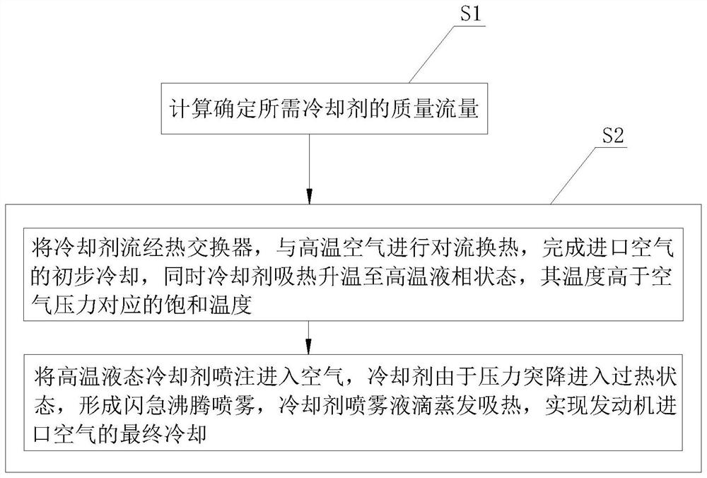
[0034] Embodiment: a kind of engine inlet air cooling method, as figure 1 As shown, it specifically includes the following steps:

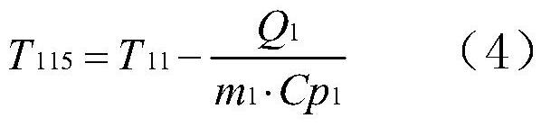
[0035] S1, according to the cooling requirement of engine inlet air, calculate and determine the flow rate of required coolant, coolant should have characteristics such as high specific heat, low boiling point, high latent heat, preferably water among coolant. The air mass flow rate at the engine inlet is m 1 , temperature T 11 , pressure P 11 , requiring cooling down to T 12 , the coolant initial temperature T 21 , pressure P 21 , flows through the heat exchanger to absorb heat and raise the temperature to T 215, and then the injection enters the air to evaporate and absorb heat. After the droplet is completely vaporized, the temperature continues to rise, and its final temperature T 22 with T 12 equal. Among them, the engine inlet air temperature T 11 Range is 400~900K, pressure P 11 0.1 ~ 0.3MPa, the air temperature T after cooling ...


PUM


Abstract

The invention discloses an engine inlet air cooling method, and relates to the technical field of aerospace power, and the technical scheme is characterized in that S1, the flow of a required coolant is determined; s2, enabling a coolant to flow through a heat exchanger, enabling the coolant to perform convection heat exchange with air at an inlet of the engine, completing primary cooling of the air, and meanwhile, enabling the coolant to absorb heat to be heated to a high-temperature liquid-phase state and enabling the temperature to be higher than saturation temperature corresponding to inlet air pressure; a high-temperature liquid coolant is sprayed into air, spray droplets evaporate and absorb heat in the air, and final cooling of the air at the inlet of the engine is achieved. Coolant flows into the heat exchanger and performs convective heat exchange with inlet air, so that the coolant absorbs heat and is heated and then sprayed into the air, the viscosity and the surface tension of the coolant are reduced along with temperature rise, meanwhile, the coolant enters an overheating state due to sudden pressure drop to form flash boiling spray, and the size of spray liquid drops is greatly reduced; therefore, coolant evaporation rate is improved, evaporation distance is shortened, and air cooling efficiency is improved.

Description

technical field [0001] The invention relates to the technical field of aerospace power, more specifically, it relates to a cooling method for engine inlet air. Background technique [0002] With the increase of the working Mach number of the aero turbine engine, the total temperature of the inlet air continues to increase, which brings a series of problems such as the operating temperature of the compressor exceeds the limit and the performance of the thermal cycle decreases, which limits the working envelope of the engine, and certain measures need to be taken To increase the working Mach number of the turbine engine. Air pre-cooling technology has been extensively studied in recent years. Adding a pre-cooling device in front of the traditional turbine engine to cool the inlet air of the compressor can prevent the air temperature from exceeding the upper limit of the compressor, and can increase the relative conversion speed of the compressor and increase the engine capacit...

Claims


Application Information

Patent Timeline
Patent Type & Authority Applications(China)
IPC IPC(8): F02B29/04
CPCF02B29/0437Y02T10/12
Inventor 张建强罗佳茂杨顺华赵延辉张顺平郑忠华
Owner 中国空气动力研究与发展中心空天技术研究所
Why Eureka
Try Eureka