Rigid-flexible coupling skin structure of shear type variable sweepback wing

A technology of rigid-flexible coupling and variable backsweep, which is applied in the aviation field to achieve the effects of improving flight efficiency, reducing energy consumption, and continuous splicing positions

Active Publication Date: 2022-03-11
HARBIN INST OF TECH
View PDF7 Cites 0 Cited by
  • Summary
  • Abstract
  • Description
  • Claims
  • Application Information

AI Technical Summary

Problems solved by technology

[0004] The purpose of the present invention is to propose a rigid-flexible coupled skin structure of a shearing variable-sweep wing in view

Method used


Image

  • Rigid-flexible coupling skin structure of shear type variable sweepback wing
  • Rigid-flexible coupling skin structure of shear type variable sweepback wing
  • Rigid-flexible coupling skin structure of shear type variable sweepback wing

Examples


specific Embodiment approach 1

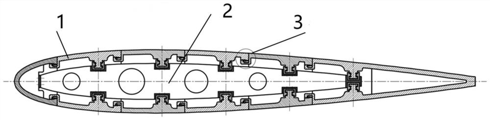
[0035] Specific implementation mode one: refer to figure 1 This embodiment is described in detail. The rigid-flexible coupling skin structure of a shear-type variable-sweep wing described in this embodiment includes a panel-type skin panel, load-bearing stringers and a sealing mechanism. The integral panel-type The skin panels are several independent units arranged in parallel, and the root of each skin panel sub-panel is connected to the fuselage through the bearing stringer lugs. The sealing structure is evenly distributed between each independent panel, and the sealing structured as Figure 7 As shown, the load-bearing stringers are glued with the integral wall panel skin surface and slide along the concave track on the support frame.

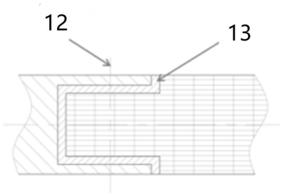
[0036] The wall panel type skin surface comprises a high temperature titanium alloy material, a rigid frame and a hexagonal honeycomb flexible structure. Alloy boundaries are joined by screws to form a siding-style skin patch. Each wall-t...

Embodiment

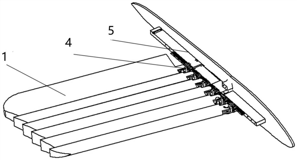
[0041] Such as figure 1 As shown, a rigid-flexible coupled skin structure of a shear-type variable-sweep wing includes a wall-type skin surface 1, a load-bearing stringer 2 and a sealing mechanism 3, and the integral wall-type skin surface 1 is several Independent units arranged in parallel, the root of each skin surface sub-surface is connected to the fuselage 5 through the bearing stringer lug 4, the sealing structure 3 is evenly distributed between each independent surface, and the bearing stringer The strip 2 is glued with the integral wall panel type skin surface 1 and slides along the concave track 6 on the support frame 8 .

[0042] Such as image 3 As shown, the skin is in the form of a wall panel skin 1, and the material is high-temperature titanium alloy, which has the characteristics of large internal space and strong bearing capacity. The hexagonal honeycomb flexible material 12 adopts a metal frame dimension 13 at the edge, and the frame 13 and After the flexibl...


PUM


Abstract

The invention discloses a rigid-flexible coupling skin structure of a shear type variable sweepback wing, relates to the technical field of aviation, and aims to solve the problem of deformation of a shear type variable sweepback wing skin in a complex force thermal environment in the prior art. The bearing framework comprises rib plates arranged in parallel and bearing stringers connected with the rib plates, the rib plates are rotationally connected with the bearing stringers, bearing stringer lugs are arranged on the bearing stringers, close to the fuselage, between the rib plates, the stringer lugs are rotationally connected with the fuselage through pin shafts, and sliding ways are machined in the rib plates; the wall plate type skin surface piece comprises a plurality of sub surface pieces, the sub surface pieces are fixedly arranged on the two adjacent rib plates, the sub surface pieces are made of high-temperature alloy materials, and the sub surface pieces are tightly arranged. The problem of adaptive deformation of the shear type variable sweepback wing skin in a complex force thermal environment is solved.

Description

technical field [0001] The invention relates to the field of aviation technology, and relates to a rigid-flexible coupled skin structure of a shear-type variable-sweep wing. Background technique [0002] Since the 1960s, the development of major technologies has been rapid. The success of high-speed missiles, space shuttles and manned spaceflight means that mankind has entered the era of supersonic speed, and future development will develop in the direction of hypersonic speed. Fixed-wing aircraft cannot fly beyond the speed of sound. By increasing the sweep angle of the wing, reducing the aspect ratio of the wing and reducing the shock wave resistance in high-speed flight to increase the flight Mach number, but the wing with a large sweep angle When flying below the speed of sound, the flight lift is relatively small, resulting in low efficiency, so swept-wing aircraft are not suitable for low-speed and long-distance flight. In order to complete different air missions, the...

Claims


Application Information

Patent Timeline
IPC IPC(8): B64C3/26B64C3/40
CPCB64C3/26B64C3/40Y02T50/40
Inventor 肖洪郭宏伟张羽李铭琦杨广刘荣强
Owner HARBIN INST OF TECH
Why Eureka
Try Eureka