Low leakage current gating switch circuit for multi-path resistance high-precision measurement

A gating switch, high-precision technology, applied in the direction of electronic switches, electrical components, pulse technology, etc., can solve the problems of inaccurate measurement, large leakage current, and inability to eliminate data processing methods, so as to reduce leakage current and leakage current Low, widely enforceable effects

Pending Publication Date: 2022-03-11
QINGDAO DONGRUAN ZAIBO INTELLIGENT ELECTRONICS
View PDF0 Cites 0 Cited by
  • Summary
  • Abstract
  • Description
  • Claims
  • Application Information

AI Technical Summary

Problems solved by technology

Moreover, the leakage current in these two places is determined by the production process of the MOS tube, which is related to the temperature, the voltage of the source and the drain, and cannot be eliminated by simple data processing methods.
In addition, as the number of gates increases, the leakage current increases
[0003] Therefore, the multi-channel strobe switch circuit in the prior art often has the problem of large leakage current and inaccurate measurement

Method used


Image

  • Low leakage current gating switch circuit for multi-path resistance high-precision measurement
  • Low leakage current gating switch circuit for multi-path resistance high-precision measurement
  • Low leakage current gating switch circuit for multi-path resistance high-precision measurement

Examples


Embodiment 1

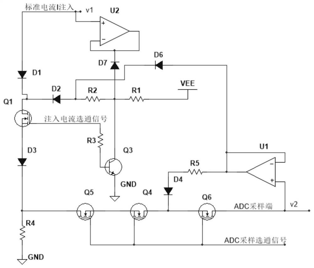
[0023] Such as image 3 As shown, Embodiment 1 of the present invention provides a low-leakage current gating switch circuit for high-precision measurement of multi-channel resistance, including: diodes D1-D7, transistor Q3, MOS transistors Q1, Q6, operational amplifiers U1, U2 .

[0024] Among them, the standard current input terminal is connected to the anode of the diode D1, the cathode of the diode D1 is connected to the drain of the MOS transistor Q1, the source of the MOS transistor Q1 is connected to the anode of the diode D3, and the gate of the MOS transistor Q1 communicates with the injection current selection The cathode of the diode D3 is grounded through the resistance R4 to be measured, the cathode of the diode D3 is also connected to the drain of the MOS transistor Q5, the source of the MOS transistor Q5 is connected to the source of the MOS transistor Q4, and the drain of the MOS transistor Q4 is connected to the The source of the MOS transistor Q6 is connecte...

Embodiment 2

[0037] Such as Figure 4 As shown, the second embodiment of the present invention provides a multi-channel resistance high-precision measurement circuit, including two gating switch circuits as described in the first embodiment. Specifically, in this embodiment, the gate switch circuits share the operational amplifiers U1 and U2.

[0038] In this embodiment, by controlling the level of the injection current gate and the ADC sampling gate in each gate switch circuit, one of the switch circuits can be controlled to perform resistance measurement, and the leakage current is small and the measurement accuracy is high. .


PUM


Abstract

The invention belongs to the technical field of circuit design, and discloses a low-leakage current gating switch circuit for multi-path resistance high-precision measurement, which comprises diodes D1-D7, a triode Q3, MOS (Metal Oxide Semiconductor) transistors Q1, Q4, Q5 and Q6, and operational amplifiers U1 and U2, a standard current input end is grounded after passing through a diode D1, an MOS tube Q1, a source electrode of the MOS tube Q1, a diode D3 and a resistor R4 to be measured, the diode D3 is further connected with an ADC sampling end through MOS tubes Q5, Q4 and Q6, a positive end of an operational amplifier U2 is connected with the standard current input end, a negative end of the operational amplifier U2 is connected with an output end, and the negative end of the operational amplifier U2 is further connected with the MOS tube Q1 through a diode D7 and a diode D2. The positive end of the operational amplifier U1 is connected with the ADC sampling end, the negative end of the operational amplifier U1 is connected with the output end, the output end of the operational amplifier U1 is connected with the diode D2 through the diode D6, and the output end of the operational amplifier U1 is further connected with the source electrode of the MOS tube Q6 through the diode D4. According to the invention, the overall leakage current of the circuit can be reduced to picoampere level, and the measurement precision is greatly improved.

Description

technical field [0001] The invention belongs to the technical field of circuit design, in particular to a low-leakage current gating switch circuit for high-precision measurement of multi-channel resistance. Background technique [0002] Measurement of resistance is a very common requirement. For the measurement of resistance, the basic method is to inject a standard current I into the resistance, and then measure the voltage V on the resistance, then the resistance value of the resistance is V / I. For the acquisition multi-channel acquisition system, there are multiple resistances to be measured, and each resistance needs to be measured in turn. Basic switching logic such as figure 1 , which resistance needs to be measured, close the corresponding two switches, and open the other switches. Here it is necessary to ensure that the switch does not introduce leakage current, so as not to affect the measurement results. The switch is implemented by a relay without introducing...

Claims


Application Information

Patent Timeline
IPC IPC(8): H03K17/687
CPCH03K17/6871H03K2217/0027
Inventor 崔健王锐胡亚军闫建国夏纯全
Owner QINGDAO DONGRUAN ZAIBO INTELLIGENT ELECTRONICS
Why Eureka
Try Eureka