Mooring multi-rotor unmanned aerial vehicle power management device and method

A multi-rotor unmanned aerial vehicle, multi-rotor unmanned aerial vehicle technology, which is applied to ground devices, circuit devices, battery circuit devices and other directions for mooring aircraft, and can solve problems such as unfavorable stagnation flight, current increase, large back electromotive force, etc. problems, to achieve the effect of protecting drones, ensuring safety, and prolonging life.

Pending Publication Date: 2022-03-15
中国兵器装备集团自动化研究所有限公司 +1
View PDF0 Cites 1 Cited by
  • Summary
  • Abstract
  • Description
  • Claims
  • Application Information

AI Technical Summary

Problems solved by technology

However, when this method acts on a high-power motor, a large back electromotive force will be generated, and the output current will also increase significantly, which will easily cause the diode to burn out
[0005] (2) The power supply used by the tethered multi-rotor UAV is all powered by the ground power supply. At this time, the airborne lithium battery needs to be equipped with an anti-backflow circuit at the output end to prevent the ground power supply from continuously supplying the airborne lithium battery. Charging, sending overcharge and causing danger. The existing anti-backflow circuit is composed of one or several diodes. The output terminal of the ground power supply is connected in series. When there are multiple diodes, they are connected in parallel to the output terminal. Although this method is simple, However, due to the large conduction voltage drop of the diode, when the output current is large, the diode will generate a large loss, that is, it is not suitable for use in a power supply with high current output.
[0006] (3) When the ground power supply equipment fails, the lithium battery in the tethered multi-rotor UAV is used as a backup power supply, and it needs to be kept at the working voltage to work normally. When the lithium battery is lower than the working voltage range, it will not be able to maintain the UAV. normal flight
The easiest way is to monitor the voltage of the onboard lithium battery through the ground station software. When it is lower than the working voltage, for the safety of the drone flight, it is necessary to lower the drone to the ground and replace the lithium battery, but this method is not conducive to long-term operation. flight of time

Method used


Image

  • Mooring multi-rotor unmanned aerial vehicle power management device and method
  • Mooring multi-rotor unmanned aerial vehicle power management device and method
  • Mooring multi-rotor unmanned aerial vehicle power management device and method

Examples


Embodiment 1

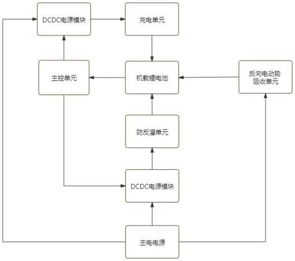
[0058] Such as figure 1 As shown, the present invention is a tethered multi-rotor unmanned aerial vehicle power management device. to ensure flight safety;

[0059] The power management device includes a main control unit, an anti-backfeed unit, a back electromotive force absorption unit, a charging unit, a DC-DC power supply module, a main power supply, an on-board lithium battery and a DC-DC power supply module; the main control unit is connected to a DC -DC power supply module, the main power supply is connected to the DC-DC power supply module, the main power supply is connected to the back electromotive force absorption unit, the DC-DC power supply module is connected to the charging unit, the DC-DC power supply module is connected to the anti-backfeed unit, and the charging unit is connected to the airborne Lithium battery, the reverse electromotive force absorption unit is connected to the onboard lithium battery, the anti-backfeed unit is connected to the onboard lith...

Embodiment 2

[0083] The difference between this embodiment and Embodiment 1 is that this embodiment provides a power management method for a tethered multi-rotor UAV, which is applied to the power management device for a tethered multi-rotor UAV. Methods include:

[0084] When the ground power supply with an external voltage of 1KV supplies power to the tethered multi-rotor drone, the voltage of the ground power supply of 1KV is first converted to the voltage of the main power supply of the tethered multi-rotor drone 50V;

[0085] The input main power supply voltage is converted to the voltage required by the charging unit and the main control unit through the DC-DC power module, and the charging unit is configured with an output voltage of 50V and a current limit of 5A; the main power supply is isolated from the onboard through the anti-backfeed unit Lithium battery to prevent backflow of the main power of the load; the backup power supply absorbs the back electromotive force through the ...


PUM


Abstract

The invention discloses a power management device and method for a mooring multi-rotor unmanned aerial vehicle, and the power management device serves as a management device for a main power supply and a standby power supply when the mooring multi-rotor unmanned aerial vehicle flies, and comprises a main control unit, a reverse irrigation prevention unit, a reverse electromotive force absorption unit, a charging unit, a main power supply and an airborne lithium battery. The charging unit is used for providing constant-current and constant-voltage charging for the airborne lithium battery through the main power supply; the anti-backflow unit is used for preventing large current from flowing back into the airborne lithium battery when the main power supply outputs the large current; the back electromotive force absorption unit is used for absorbing back electromotive force generated by a motor on an arm of the mooring multi-rotor unmanned aerial vehicle into an airborne lithium battery; the main control unit is used for acquiring voltage, current and temperature data of the airborne lithium battery in real time through an I2C bus; and the state information of the airborne lithium battery, the charging current, the anti-backflow state and the number of times of reverse electromotive force absorption are fed back to the mooring multi-rotor unmanned aerial vehicle ground station through a CAN bus interface.

Description

technical field [0001] The invention relates to the technical field of UAV power management, in particular to a tethered multi-rotor UAV power management device and method. Background technique [0002] The tethered multi-rotor drone is a new type of drone that combines a multi-rotor drone with a tethered integrated cable. The essential difference between it and ordinary multi-rotor drones is that the power supply mode is changed from the onboard lithium battery to the direct power supply on the ground. Stay in the air for a long time due to power limitation. Solving the endurance problem of ordinary multi-rotor UAVs, tethered multi-rotor UAVs are considered to be a major trend in the development of UAVs in the future. [0003] Existing technology has the following problems: [0004] (1) During the flight, since the motor in the UAV arm has fast response, start and stop, and when it suddenly decelerates from a high speed, the change of the instantaneous current of the mot...

Claims


Application Information

Patent Timeline
IPC IPC(8): B64F3/02B64D27/24H02M3/04H02J7/00
CPCB64F3/02B64D27/24H02M3/04H02J7/0047Y02T50/60
Inventor 罗志豪章百宝李恒程子恒孙春然胡俊雷超张春华
Owner 中国兵器装备集团自动化研究所有限公司
Why Eureka
Try Eureka