On-orbit self-calibration device of satellite-borne laser communication machine and calibration method of on-orbit self-calibration device

A communication machine and laser technology, applied in satellite communication transmission, optical fiber transmission, free space transmission, etc., can solve the problems of difficult satellite-ground calibration and long calibration time, reduce debugging time, and solve self-calibration problems Effect

Active Publication Date: 2022-03-15
ZHEJIANG LAB
View PDF8 Cites 4 Cited by
  • Summary
  • Abstract
  • Description
  • Claims
  • Application Information

AI Technical Summary

Problems solved by technology

[0004] The purpose of the present invention is to provide an on-orbit self-calibration device and calibration method for a space-borne laser communication machine for the deficiencies in the prior art, which can realize the on-orbit self-calibration of a non-beacon optical space-borne laser communication machine , to solve the problems of star-earth calibration difficulty and long calibration time existing in the existing base

Method used


Image

  • On-orbit self-calibration device of satellite-borne laser communication machine and calibration method of on-orbit self-calibration device
  • On-orbit self-calibration device of satellite-borne laser communication machine and calibration method of on-orbit self-calibration device
  • On-orbit self-calibration device of satellite-borne laser communication machine and calibration method of on-orbit self-calibration device

Examples


Embodiment Construction

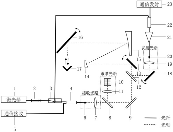
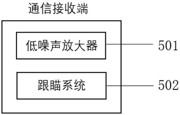
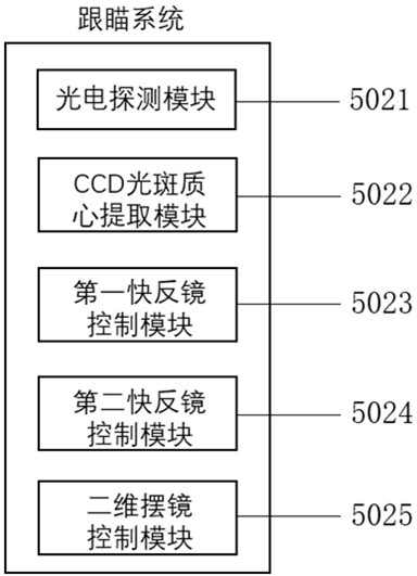
[0025] Reference will now be made in detail to the exemplary embodiments, examples of which are illustrated in the accompanying drawings. When the following description refers to the accompanying drawings, the same numerals in different drawings refer to the same or similar elements unless otherwise indicated. The implementations described in the following exemplary examples do not represent all implementations consistent with the present invention. Rather, they are merely examples of apparatuses and methods consistent with aspects of the invention as recited in the appended claims.

[0026] The terminology used in the present invention is for the purpose of describing particular embodiments only and is not intended to limit the invention. As used herein and in the appended claims, the singular forms "a", "the", and "the" are intended to include the plural forms as well, unless the context clearly dictates otherwise. It should also be understood that the term "and / or" as use...


PUM

PropertyMeasurementUnit
Clear apertureaaaaaaaaaa

Abstract

The invention discloses an on-orbit self-calibration device of a satellite-borne laser communication machine and a calibration method of the on-orbit self-calibration device. Comprising a laser, an optical fiber isolator, an optical switch, a first optical fiber coupler, a communication receiving end, a receiving optical fiber, a receiving lens group, a beam splitter, a reflector, a tracking and pointing detector, a tracking and pointing lens group, a color separation film, a first fast reflecting mirror, a secondary mirror, a primary mirror, a two-dimensional oscillating mirror, a pyramid, a second fast reflecting mirror, a transmitting lens group, a transmitting optical fiber and a high-power amplifier. And a second optical fiber coupler and a communication transmitting terminal. According to the invention, the optical switches are sequentially turned on to the receiving optical path or the transmitting optical path, and then are reflected to the receiving optical path through the pyramid to detect the optical power, and the tracking and pointing optical path is used for detecting and compensating the mass center position of a light spot, so that the coaxial self-calibration of the receiving optical path, the transmitting optical path and the tracking and pointing optical path is realized. The tracking and pointing precision and the link transmission efficiency are improved, and the debugging difficulty and accuracy of the laser communication machine during satellite in-orbit operation are reduced.

Description

technical field [0001] The invention belongs to the technical field of space-borne laser communication equipment, and relates to an on-orbit self-calibration device of a space-borne laser communication device and a calibration method of the above-mentioned self-calibration device. Background technique [0002] Space laser communication refers to a communication method that uses laser as an information carrier and the atmosphere as a transmission channel to realize wireless transmission of voice, data, images and other information in space. It combines the characteristics of optical fiber communication and microwave communication. With the communication performance of high communication rate, large communication capacity, strong anti-interference ability and strong anti-interception ability, it also conforms to the development trend of satellite miniaturization and light weight, and has become An emerging broadband wireless access method with great potential has huge applicat...

Claims


Application Information

Patent Timeline
IPC IPC(8): H04B10/118H04B10/25
CPCH04B10/118H04B10/25
Inventor 黄雅莉汪逸群赵海平王云飞侯月
Owner ZHEJIANG LAB
Why Eureka
Try Eureka