Active resonant fiber-optic gyroscope

A fiber optic gyroscope and source resonance technology, which is applied to Sagnac effect gyroscopes, gyroscopes/steering sensing equipment, instruments, etc., can solve problems such as low gain of the resonant cavity, lock-up, etc., to compensate loss and improve signal-to-noise ratio , strong feasibility and practical effect

Active Publication Date: 2022-03-18
BEIHANG UNIV
View PDF4 Cites 2 Cited by
  • Summary
  • Abstract
  • Description
  • Claims
  • Application Information

AI Technical Summary

Problems solved by technology

[0005]However, the gain in the resonant cavity of the current active resonant gyro scheme is low, which requires the light source to have characteristics such as narrow line width, high power, and high stability of wavelength and power. In order to generate stable laser light in a short fiber ring cavity
At the same time, it also has the same latch-up problem as the traditional laser gyro

Method used


Image

  • Active resonant fiber-optic gyroscope
  • Active resonant fiber-optic gyroscope
  • Active resonant fiber-optic gyroscope

Examples


Embodiment Construction

[0031] In order to understand the above-mentioned purpose, features and advantages of the present invention more clearly, the present invention will be further described in detail below in conjunction with the accompanying drawings and specific embodiments. It should be noted that, in the case of no conflict, the embodiments of the present invention and the features in the embodiments can be combined with each other.

[0032] In the following description, many specific details are set forth in order to fully understand the present invention. However, the present invention can also be implemented in other ways different from those described here. Therefore, the protection scope of the present invention is not limited by the specific details disclosed below. EXAMPLE LIMITATIONS.

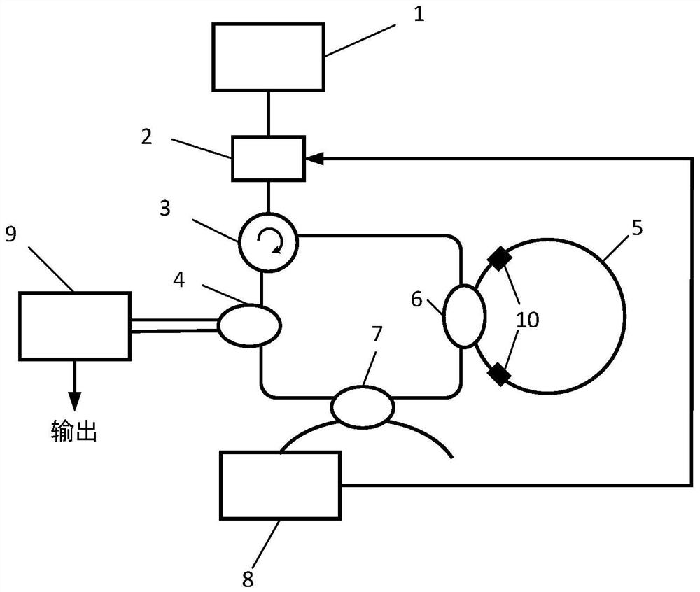
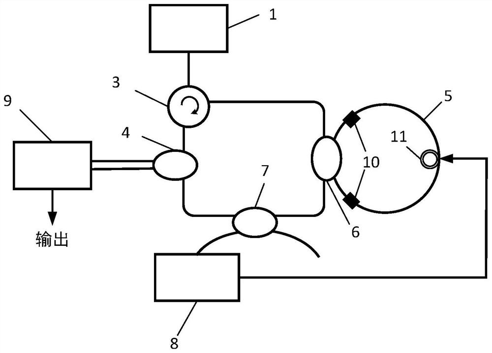
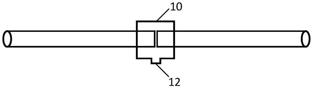
[0033] In the traditional active resonant fiber optic gyro scheme, the resonant cavity is an ordinary optical fiber. This scheme is a gas-filled photonic crystal fiber. On the premise of ensuring the a...


PUM


Abstract

The invention discloses an active resonant fiber-optic gyroscope, which comprises a laser light source, a phase modulator, a circulator, a first coupler, a gas-filled photonic crystal fiber resonant cavity, a second coupler, a third coupler, an FPGA (Field Programmable Gate Array) module and a signal processing system. The photonic crystal fiber filled with gas is adopted as a resonant cavity to increase gain, the problem of poor stability caused by non-uniform laser beam splitting is solved through one-way pump light input, and the blocking effect in an original scheme can be solved by performing angular velocity sensitivity through the cascaded Brillouin laser output reversely.

Description

technical field [0001] The invention belongs to the technical field of fiber optic gyroscopes, in particular to a gas-filled active resonant fiber optic gyroscope. Background technique [0002] Fiber optic gyroscope (FOG) is a new type of inertial device based on the Sagnac effect in optical fiber to sense the rotational angular velocity. The Sagnac effect is a phenomenon in which the angular rate of external rotation affects the interference of light: in a closed optical loop, two beams of light waves that propagate in opposite directions from any point in a closed optical loop return to this point after traveling for a week , the phase of the two light waves will change with the rotation of the relative inertial space, which is the theoretical basis of all optical gyroscopes. [0003] So far, it has experienced three generations of development: interferometric (I-FOG), resonant (R-FOG) and Brillouin (BFOG). Among them, the interferometric fiber optic gyroscope has been s...

Claims


Application Information

Patent Timeline
Patent Type & Authority Applications(China)
IPC IPC(8): G01C19/72
CPCG01C19/721G01C19/725
Inventor 徐小斌柳辰琛宋凝芳高福宇杨合高乘春
Owner BEIHANG UNIV
Why Eureka
Try Eureka