Ductile iron pouring system with filtering and positioning device and use method of ductile iron pouring system

A pouring system and positioning device technology, which is applied in the direction of manufacturing tools, casting molding equipment, mechanical cleaning, etc., can solve problems such as difficult to achieve gapless bonding, high labor intensity for slag removal, and waste of raw materials, so as to avoid low prices The effects of selling out, saving electricity time, and improving styling efficiency

Active Publication Date: 2022-03-22
大连华锐重工铸业有限公司 +1
View PDF12 Cites 1 Cited by
  • Summary
  • Abstract
  • Description
  • Claims
  • Application Information

AI Technical Summary

Problems solved by technology

However, in the actual production process, it is found that it is difficult to fit the cover plate core and the sand mold without gaps during assembly. During the pouring process, molten iron penetrates through the gap, so that the horizontal gate and the cover plate sand core are often completely wrapped by molten iron. The formation of sintered "iron-sand mixture" brings great difficulty to the cleaning of castings, which is also the root cause of the sand sticking problem at the horizontal gate of this project
Due to the defect of sticky sand in the pouring system, the recycled material is forced to be graded. The low-grade recycled material that is barely reused will generate more scum during the smelting process, and it will take a lot of man-hours to remove the slag, which directly prolongs the smelting time, resulting in In addition to the increase in electricity costs, the labor intensity of slag removal at high temperatures is extremely high, and the returned materials with severe sand stickiness are forced to be used as residual materials and sold at a reduced price, resulting in waste of raw materials and greatly increasing the cost of returning to the furnace

Method used


Image

  • Ductile iron pouring system with filtering and positioning device and use method of ductile iron pouring system
  • Ductile iron pouring system with filtering and positioning device and use method of ductile iron pouring system
  • Ductile iron pouring system with filtering and positioning device and use method of ductile iron pouring system

Examples


Embodiment 1

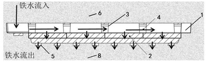
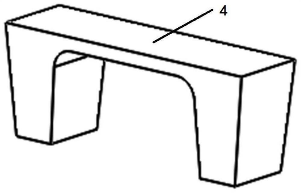
[0043] Such as Figure 1~4 As shown, a ductile iron gating system with a filter positioning device includes a gating system 1, the gating system is in the shape of a stepped groove, and is divided into an upper groove and a lower groove; there are multiple gating systems along the lower groove The filter screen 2 closely arranged in the length direction of 1, the groove wall of the upper groove has a protruding positioning notch 3 between two adjacent filter nets 2, and there is an upper The filter screen positioning device 4 in the groove; the filter screen positioning device 4 adopts a gantry structure, and the arrangement direction of the two legs at the bottom is parallel to the width direction of the pouring system 1, and the outer side of each leg is in line with the upper groove. The groove bottom is contacted and connected, and the inner side of the leg is located above the filter screen 2, and there is a gap of 1-2mm between the filter screen 2, so as to prevent the f...

Embodiment 2

[0045] Such as Figure 1~4 As shown, a method for using a ductile iron pouring system with a filter positioning device, including:

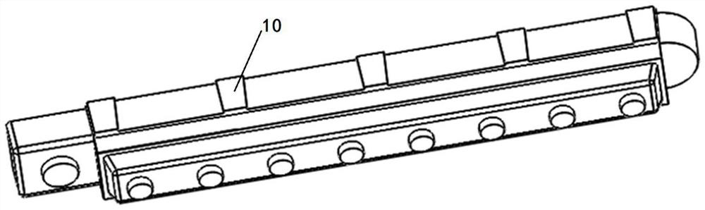
[0046] (1) Prepare the gating system model 7, set the protrusion 10 according to the placement position of the filter screen 2, and the protrusion 10 forms the positioning notch 3 of the gating system 1; The gating system model 7 is made of wood material.

[0047] (2) prepare the filter screen positioning device 4 that matches with the positioning notch 3; the filter screen positioning device 4 can be a standard part, and it must not have depressions or protrusions or cracks; the design of the positioning notch 3 can reserve 1~ 2mm assembly clearance;

[0048] (3) Place the gating system model 7 according to the requirements of the casting process drawings, and complete the assembly with other components such as the ceramic pouring pipe 5, start the sand filling molding, sink the gating system model 7 into the lower sand mold 8, and use manual ...


PUM

PropertyMeasurementUnit
flame retardantaaaaaaaaaa
porosityaaaaaaaaaa

Abstract

The invention provides a ductile iron pouring system with a filtering and positioning device and a using method thereof.The ductile iron pouring system comprises a pouring system body, and the pouring system body is in a stepped groove shape and is divided into an upper groove and a lower groove; a plurality of filter screens which are tightly arranged in the length direction of the pouring system are arranged in the lower groove; the groove wall of the upper groove is provided with a convex positioning spigot between two adjacent filter screens, and a filter screen positioning device mounted in the upper groove is arranged between two opposite positioning spigots; the filter screen positioning device is of a gantry type structure, the arrangement direction of two supporting legs at the bottom of the filter screen positioning device is parallel to the width direction of the pouring system, the outer side of each supporting leg is in contact connection with the groove bottom of the upper groove, the inner side of each supporting leg is located above the filter screen, and a gap of 1-2 mm is formed between the inner side of each supporting leg and the filter screen. Cover plate sand core modeling is omitted, the model manufacturing cost is reduced, the modeling work efficiency is improved, the cover plate sand core does not need to be researched during box closing, and the operation difficulty is reduced.

Description

technical field [0001] The invention relates to the technical field of casting and pouring systems for wind power ductile iron parts, in particular to a ductile iron pouring system with a filter positioning device and a method for using the same. Background technique [0002] Wind power ductile iron parts have extremely high requirements on product surface quality, and the acceptance level of MT flaw detection can reach level 2, or even level 1. In order to meet such quality requirements, the purity of molten iron must be guaranteed as much as possible. For this reason, the casting pouring system is equipped with a ceramic filter screen to filter the molten iron. At the same time, in order to prevent the filter screen from floating or shifting during the washing process of the molten iron, the traditional process design uses a cover plate sand core to press the filter screen, which is effective. Realized the purification purpose of molten iron. The cover plate sand core an...

Claims


Application Information

Patent Timeline
Patent Type & Authority Applications(China)
IPC IPC(8): B22C9/08B22D43/00
CPCB22C9/082B22C9/086Y02P10/20
Inventor 荀诗文杨继伟郑永杰李云飞刘毅刘广升
Owner 大连华锐重工铸业有限公司
Why Eureka
Try Eureka