
Electromagnetic air heater

A hot air blower and electromagnetic technology, applied in the direction of air heaters, fluid heaters, lighting and heating equipment, etc., can solve the problems of not effectively increasing the air temperature, increasing the loss of air kinetic energy, and not effectively using heat, etc. Thermally efficient, extended flow distance, long flow distance effect

Pending Publication Date: 2022-03-25
广东念智节能科技有限公司
View PDF13 Cites 0 Cited by
  • Summary
  • Abstract
  • Description
  • Claims
  • Application Information

AI Technical Summary

Problems solved by technology

[0003] In order to increase the heat exchange area, some metal air ducts are equipped with fins in the radial direction to improve heat exchange efficiency, but adding radial fins cannot effectively increase the air temperature in the area near the axis of the air duct; After the fins are installed in the direction, a spoiler is installed at the air inlet of the metal air duct to make the air flow turbulent, but the air will become laminar flow instead of turbulent flow after a certain distance, and the turbulence effect is not great. It is not ideal and increases the kinetic energy loss of the air, which increases the operating cost
[0004] The high-frequency current of the induction coil heats the metal air cylinder, but the temperature distribution of the metal air cylinder is the highest outside temperature, and the temperature decreases near the center. The known air cylinder structure makes air flow in the part of the air cylinder near the outside, and the metal air cylinder Although the temperature of the axis area is lower than that of the outer side, it is much higher than the room temperature. This part of the heat is not effectively used, resulting in energy waste

Method used


Image

  • Electromagnetic air heater
  • Electromagnetic air heater
  • Electromagnetic air heater

Examples


Embodiment Construction

[0039] The specific embodiments of the present invention will be further described below in conjunction with the accompanying drawings. It should be noted here that the descriptions of these embodiments are used to help understand the present invention, but are not intended to limit the present invention. In addition, the technical features involved in the various embodiments of the present invention described below may be combined with each other as long as they do not constitute a conflict with each other.

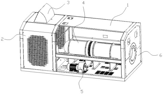
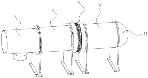
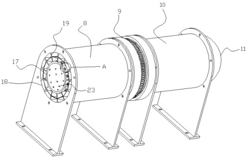
[0040] Such as figure 1 Shown, a kind of electromagnetic heating air blower comprises: frame 1 and electromagnetic heating air duct 4, electric control box 2 is set on the side of frame 1, console 3 is installed on the top of electric control box 2; Electromagnetic heating air duct 4 Installed inside the frame 1 through a support frame; the electromagnetic heating air cylinder 4 includes: an air inlet and outlet assembly 7 , a heating cylinder, a shaftless fan 9 and a r...


PUM

PropertyMeasurementUnit
Heightaaaaaaaaaa

Abstract

The invention relates to the technical field of electromagnetic induction heating equipment, and particularly discloses an electromagnetic air heater which comprises a rack and an electromagnetic heating air duct, and the electromagnetic heating air duct comprises an air inlet and outlet assembly; the fan is used for inputting cold air and outputting hot air; an electromagnetic coil is wound on the outer side of the heating barrel, the heating barrel is used for preheating cold air and heating the preheated cold air into hot air, the heating barrel comprises a first heating gun barrel and a second heating gun barrel, an inner barrel and an outer barrel which are communicated with each other are arranged in the first heating gun barrel and the second heating gun barrel respectively, a preheating cavity is formed in the inner barrel, and a heating cavity is formed in the outer barrel. The outer wall of the inner barrel is connected with the inner wall of the outer barrel through a plurality of partition plates, an independent heat exchange cavity is formed between every two adjacent partition plates, and a flow guide assembly used for prolonging the hot air flowing distance is arranged in each heat exchange cavity; the electromagnetic air heater increases the heating area, can greatly improve the heat exchange efficiency by being matched with the preheating cavity, effectively utilizes the heat of the inner cylinder, and reduces the waste of energy.

Description

technical field [0001] The invention relates to the technical field of electromagnetic induction heating equipment, specifically, an electromagnetic heating fan. Background technique [0002] At present, known electromagnetic heaters or electromagnetic heaters use electromagnetic coils to wind metal air cylinders, and the metal air cylinders are heated by high-frequency currents. And then generate hot air, so that the hot air is used for drying products. [0003] In order to increase the heat exchange area, some metal air ducts are equipped with fins in the radial direction to improve heat exchange efficiency, but adding radial fins cannot effectively increase the air temperature in the area near the axis of the air duct; After the fins are installed in the direction, a spoiler is installed at the air inlet of the metal air duct to make the air flow turbulent, but the air will become laminar flow instead of turbulent flow after a certain distance, and the turbulence effect ...

Claims


Application Information

Patent Timeline
IPC IPC(8): F24H3/04F24H9/1863F24H9/20
CPCF24H3/04F24H9/1863F24H9/2071Y02E20/34
Inventor 张火炬庞长兴国熠
Owner 广东念智节能科技有限公司
Features
  • Generate Ideas
  • Intellectual Property
  • Life Sciences
  • Materials
  • Tech Scout
  • Unparalleled Data Quality
  • Higher Quality Content
  • 60% Fewer Hallucinations
Learn More