Graphene grounding system

A grounding system and graphene technology, applied in the direction of connecting contact materials, etc., can solve the problems of peeling, welding position breakage, easy local falloff, etc., achieve strong bearing capacity and impact resistance, improve installation efficiency, and reduce damage rate Effect

Pending Publication Date: 2022-03-25
HAINAN POWER GRID CO LTD ELECTRIC POWER RES INST
View PDF0 Cites 0 Cited by
  • Summary
  • Abstract
  • Description
  • Claims
  • Application Information

AI Technical Summary

Problems solved by technology

[0002] The mandrels of the grounding system in the existing market are generally directly coated with a layer of copper on the outer surface of the steel rods, that is, the copper-clad steel structure. Although the mandrels of this structure have achieved good electrical conductivity, high mechanical strength and Good corrosion resistance, however, due to the obvious difference in metallographic structure between the copper material and the steel material, the adhesion between the copper layer and the steel rod surface is not enough, resulting in that the copper layer is easily localized after covering the steel rod surface. In addition, since the grounding system generally needs to drive the mandrel into the wet soil layer at least during installation, it requires multiple mandrels connected together, and driven into the soil layer, but the connection between the mandrels in the prior art mainly relies on welding and drilling to lock the screws, which makes the mandrel when the installer knocks the mandrel into the soil layer The connection position between the mandrel and the mandrel is subjected to a great impact force. In the process of repeated beating, it is very easy to cause the welding position to break or the screw to break, and then all previous efforts are wasted, which greatly affects the installation efficiency and operation of the staff. process

Method used


Image

  • Graphene grounding system
  • Graphene grounding system

Examples


Embodiment Construction

[0016] The following will clearly and completely describe the technical solutions in the embodiments of the present invention with reference to the accompanying drawings in the embodiments of the present invention. Obviously, the described embodiments are only some, not all, embodiments of the present invention. Based on the embodiments of the present invention, all other embodiments obtained by persons of ordinary skill in the art without making creative efforts belong to the protection scope of the present invention.

[0017] The object of the present invention is to provide a stone graphene grounding system with simple structure, reliable use and easy installation.

[0018] In order to make the above objects, features and advantages of the present invention more comprehensible, the present invention will be further described in detail below in conjunction with the accompanying drawings and specific embodiments.

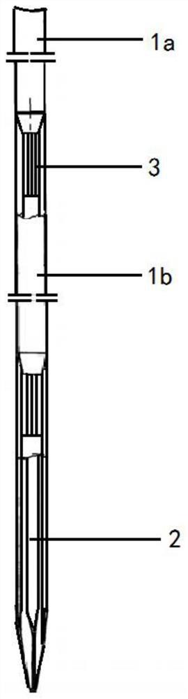
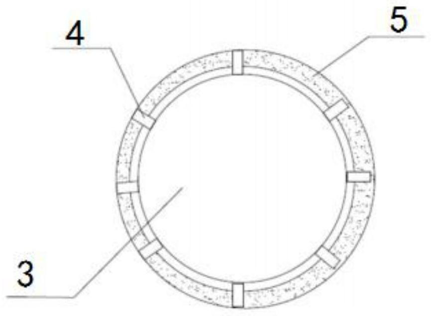
[0019] Such as Figure 1-2 As shown, the graphene grounding ...


PUM


Abstract

The invention discloses a graphene grounding system which comprises at least two core rods and a coating drill bit, and the coating drill bit is sequentially provided with a first graphene layer, a foaming anti-corrosion layer and a second graphene layer from inside to outside. A core rod connector is arranged at the connecting end of the core rod and the plating drill bit, and the radius of the core rod connector is smaller than that of the core rod. A plurality of convex edges are arranged on the core rod connector, a clamping groove is formed in the coating drill bit, and the convex edges are clamped in the clamping groove in a sleeved mode. Through the first graphene layer, the foaming anti-corrosion layer and the second graphene layer, the strength is more than 1000 times that of copper, and the good anti-corrosion effect is achieved; a plurality of convex edges are arranged on the core rod joint, so that the connection effect and the contact are better, the core rod shows more reliable and stable characteristics under the continuous driving of the electric hammer, the effect of reducing the damage rate is achieved, the installation efficiency of workers is effectively improved, and the service life of a grounding system is effectively prolonged.

Description

technical field [0001] The invention relates to the technical field of power facilities, in particular to a graphene grounding system. Background technique [0002] The mandrels of the grounding system in the existing market are generally directly coated with a layer of copper on the outer surface of the steel rods, that is, the copper-clad steel structure. Although the mandrels of this structure have achieved good electrical conductivity, high mechanical strength and Good corrosion resistance, however, due to the obvious difference in metallographic structure between the copper material and the steel material, the adhesion between the copper layer and the steel rod surface is not enough, resulting in that the copper layer is easily localized after covering the steel rod surface. In addition, since the grounding system generally needs to drive the mandrel into the wet soil layer at least during installation, it requires multiple mandrels connected together, and driven into ...

Claims


Application Information

Patent Timeline
Patent Type & Authority Applications(China)
IPC IPC(8): H01R4/66
CPCH01R4/66
Inventor 符方达王晨东吴育毅
Owner HAINAN POWER GRID CO LTD ELECTRIC POWER RES INST
Why Eureka
Try Eureka