Radio frequency channel real-time protection and undistorted transmission circuit suitable for ultra-short wave frequency band and configuration method of radio frequency channel real-time protection and undistorted transmission circuit

A technology of radio frequency channel and transmission circuit, which is applied in the layout of amplifier protection circuit, transmission system, radio frequency amplifier, etc. It can solve the problems of high price, non-adjustable gain, and low input power against burnout, and achieve low production cost and accurate gain and clipping level controls, versatile effects

Pending Publication Date: 2022-03-29
MIANYANG NETOP TELECOM EQUIP
View PDF0 Cites 0 Cited by
  • Summary
  • Abstract
  • Description
  • Claims
  • Application Information

AI Technical Summary

Problems solved by technology

The traditional radio frequency circuit uses MMIC, the gain is not adjustable, the maximum anti-burnout input power is small, and the price is relatively expensive

Method used


Image

  • Radio frequency channel real-time protection and undistorted transmission circuit suitable for ultra-short wave frequency band and configuration method of radio frequency channel real-time protection and undistorted transmission circuit
  • Radio frequency channel real-time protection and undistorted transmission circuit suitable for ultra-short wave frequency band and configuration method of radio frequency channel real-time protection and undistorted transmission circuit
  • Radio frequency channel real-time protection and undistorted transmission circuit suitable for ultra-short wave frequency band and configuration method of radio frequency channel real-time protection and undistorted transmission circuit

Examples


Embodiment Construction

[0031] The present invention will be further described in detail below in conjunction with the accompanying drawings, so that those skilled in the art can implement it with reference to the description. It should be understood that terms such as "having", "comprising" and "including" used herein do not exclude the presence or addition of one or more other elements or combinations thereof.

[0032] It should be noted that in the description of the present invention, the orientation or positional relationship indicated by the term is based on the orientation or positional relationship shown in the drawings, which is only for the convenience of describing the present invention and simplifying the description, and does not indicate or imply No device or element must have a specific orientation, be constructed, and operate in a specific orientation and therefore should not be construed as limiting the invention. In the description of the present invention, unless otherwise clearly ...


PUM


Abstract

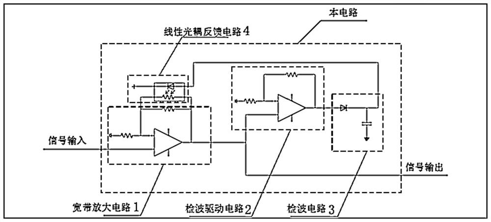
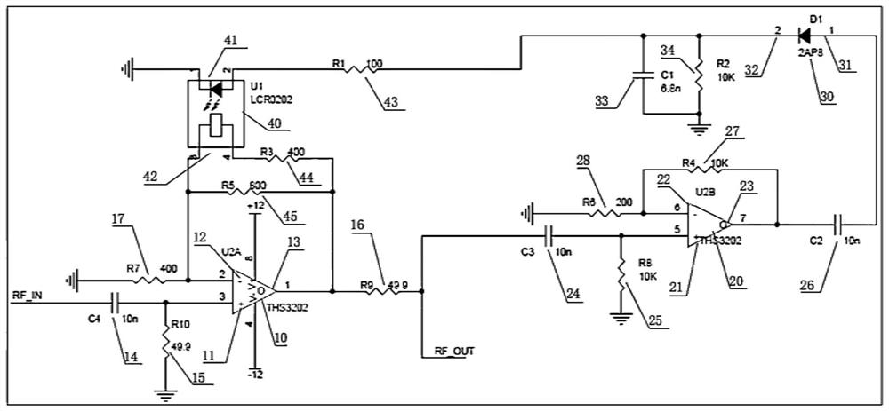
The invention discloses a radio frequency channel real-time protection and undistorted transmission circuit suitable for an ultrashort wave frequency band and a configuration method thereof, and the circuit comprises a broadband amplification circuit, the in-phase input end and output end of which are respectively connected with an RFIN and an output RFOUT; the in-phase input end of the detection driving circuit is connected to the output end of the broadband amplification circuit; the input end of the detection circuit is connected to the output end of the detection driving circuit; and the input end and the output end of the linear optocoupler feedback circuit are respectively butted with the output end of the detection circuit and the inverted input end of the broadband amplification circuit. The circuit can work in a frequency band of 30MHz-88MHz, can be used for a driving end of a radio frequency power amplifier of an ultra-short wave radio station, and can also be used for anti-burning of a receiving channel of the ultra-short wave radio station and input protection of intermediate frequencies of ADC ends of various receivers. Comprising a low-noise broadband current feedback operational amplifier, a linear optocoupler and the like. The low-noise broadband current feedback operational amplifier has the advantages that the working frequency is high, the anti-burning power can reach 2W, the gain adjustment is convenient, the price is low, and the like.

Description

technical field [0001] The invention relates to the field of ultra-short-wave frequency band communication, in particular to a radio frequency channel real-time protection and distortion-free transmission circuit suitable for ultra-short-wave frequency band and a configuration method thereof. Background technique [0002] The VHF ultrashort wave generally uses the 30MHz-88MHz frequency band, which is used for the radio frequency channel of the ultrashort wave radio station and the intermediate frequency signal processing of various wireless receivers. The traditional radio frequency circuit uses MMIC, the gain is not adjustable, the maximum anti-burnout input power is small, and the price is relatively expensive. [0003] The invention discloses a real-time protection circuit for a radio frequency channel in an ultrashort wave frequency band. Working in the 30MHz-88MHz frequency band, it can be used for the drive end of the RF power amplifier of the ultrashort wave radio st...

Claims


Application Information

Patent Timeline
Patent Type & Authority Applications(China)
IPC IPC(8): H03F1/32H03F1/52H03F3/195H04B1/40
CPCH03F1/32H03F1/52H03F3/195H04B1/40H03F2200/451
Inventor 朱佩涛于国洪罗文彬旷小兵赵为民
Owner MIANYANG NETOP TELECOM EQUIP
Why Eureka
Try Eureka