Flue gas denitration system of thermal power generating unit and control method

A thermal power unit and control method technology, applied in the field of flue gas denitrification, can solve the problems of high operating cost, less ammonia escape, air preheater blockage, etc., and achieve the effect of meeting environmental protection requirements, less ammonia escape, and improving accuracy

Pending Publication Date: 2022-04-05
HUANENG LINYI POWER GENERATION CO LTD
View PDF0 Cites 0 Cited by
  • Summary
  • Abstract
  • Description
  • Claims
  • Application Information

AI Technical Summary

Problems solved by technology

[0003] With the large-scale grid-connection of photovoltaic power generation and wind power generation, thermal power units have changed from bearing basic loads to flexible operation. Operations such as frequent start-up and shutdown of units and rapid load reduction have brought adverse effects on the flue gas denitrification system, and ammonia injection is prone to occur. If the amount of ammonia injection is too large, the amount of ammonia escaped from the flue gas denitrification system will be large, and the operating cost will be high, which will easily lead to clogging and corrosion of the air preheater, dust accumulation and jamming of the rotor blades of the induced draft fan, etc., affecting The load capacity of the unit threatens the safe and stable operation of the unit. If the amount of ammonia injection is insufficient, the concentration of nitrogen oxides in the flue gas will be high, which cannot meet the environmental protection requirements.
[0004] Under different loads, the distribution of the flue gas flow field is different. It is difficult to adapt to the current unit operation requirements by manually adjusting the amount of ammonia injection. There is an urgent need for an automatic control of the amount of ammonia injection according to different loads and different working conditions. A thermal power unit flue gas denitrification system and control method with high effectiveness of ammonia injection, high utilization rate, and less ammonia escape, which can meet environmental protection requirements

Method used


Image

  • Flue gas denitration system of thermal power generating unit and control method
  • Flue gas denitration system of thermal power generating unit and control method

Examples


Embodiment Construction

[0026] The preferred embodiments of the present invention will be described in detail below in conjunction with the accompanying drawings, so that the advantages and features of the present invention can be more easily understood by those skilled in the art, so as to define the protection scope of the present invention more clearly.

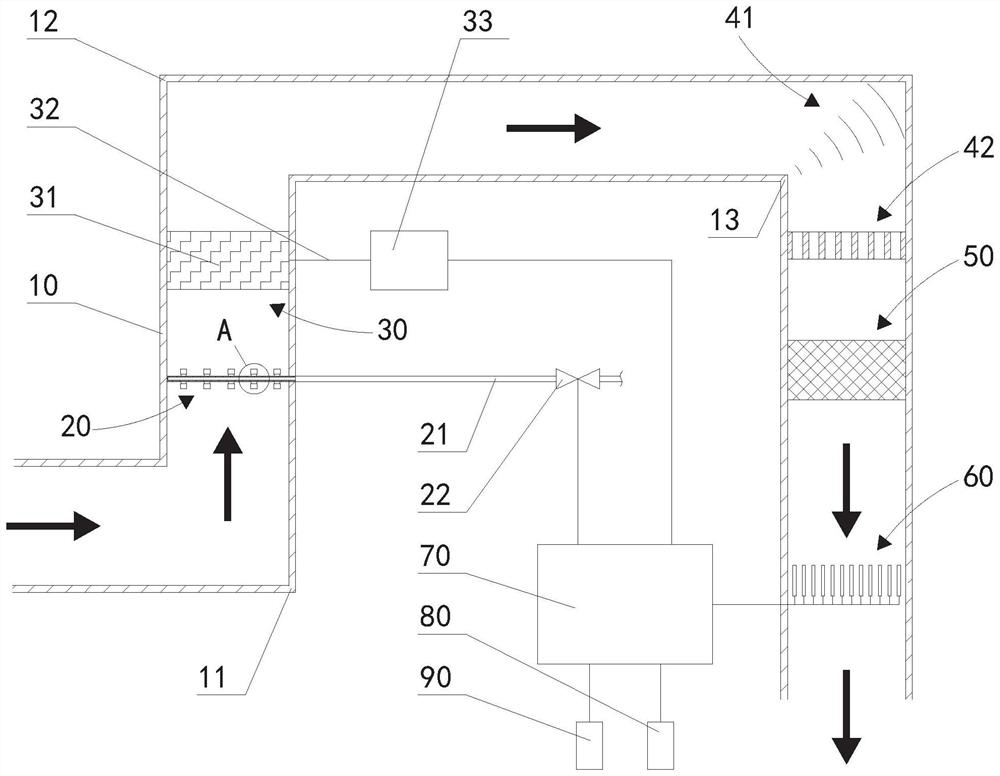
[0027] The up-down direction described in the present invention is figure 1 In the up and down direction, the present invention describes the flue gas flow direction as figure 1 The direction indicated by the arrow in the middle flue.

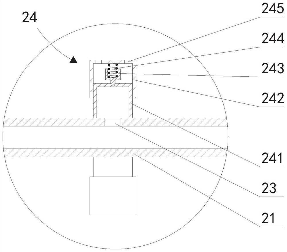
[0028] Such as figure 1 and figure 2 As shown, the flue gas denitrification system for thermal power units provided by the present invention includes: a flue 10 and an ammonia injection grid 20, a mixer 30, a flow guiding device 41, and a rectifying device arranged in the flue 10 in sequence along the flue gas flow direction 42. The catalytic device 50 and the NOx measuring device 60, wherein the flue 10 is ar...


PUM


Abstract

The flue gas denitration system of the thermal power generating unit comprises a flue, an ammonia spraying grid, a mixer, a flow guiding device, a rectifying device, a catalyzing device and a NOx measuring device, and a control device is electrically connected with a proportioning valve of the ammonia spraying grid, the NOx measuring device, a coal quality measuring device and a unit load measuring device; according to the control method, feedback control can be carried out on the opening degree of the proportioning valve according to the concentration of NOx, and feedforward control can be carried out on the opening degree of the proportioning valve according to the quality of coal as fired and the load of a unit, so that the technical effect of automatically controlling the ammonia spraying amount according to different loads and different working conditions is achieved; according to the control method, the ammonia spraying amount can be adjusted in advance, the ammonia spraying effectiveness is high, the utilization rate is high, the ammonia escape amount is small, the environmental protection requirement can be met, according to the control method, the unit characteristics which do not fall into the database are subjected to feedback adjustment and supplemented into the database, continuous improvement and correction can be achieved, and therefore the accuracy of pre-adjustment is improved.

Description

technical field [0001] The invention relates to the technical field of flue gas denitration, in particular to a flue gas denitrification system and a control method of a thermal power unit. Background technique [0002] Nitrogen oxides (NOx) are a class of major air pollutants and one of the main factors that form acid rain, photochemical smog and PM2.5 pollution. In industrial flue gas treatment, common NOx emission control technologies include selective catalytic reduction (SCR), Selective Non-Catalytic Reduction (SNCR) and SCR-SNCR hybrid technologies, Selective Catalytic Reduction (SCR) technology has the characteristics of high efficiency, no secondary pollution, and mature technology, and is widely used in large coal-fired units . [0003] With the large-scale grid-connection of photovoltaic power generation and wind power generation, thermal power units have changed from bearing basic loads to flexible operation. Operations such as frequent start-up and shutdown of u...

Claims


Application Information

Patent Timeline
Patent Type & Authority Applications(China)
IPC IPC(8): B01D53/88B01D53/86B01D53/56
Inventor 段传洋张海龙谢东晴蒋伯振段传钰马玉杰
Owner HUANENG LINYI POWER GENERATION CO LTD
Why Eureka
Try Eureka