Automatic IED chip wire welding device
A wire bonding device and chip technology, which is applied in the field of wire bonding machines, can solve problems such as inaccurate placement, sore eyes, burns, etc., and achieve the effect of uniform length, precise position, and cleanliness
- Summary
- Abstract
- Description
- Claims
- Application Information
AI Technical Summary
Problems solved by technology
Method used
Image
Examples
Embodiment 1
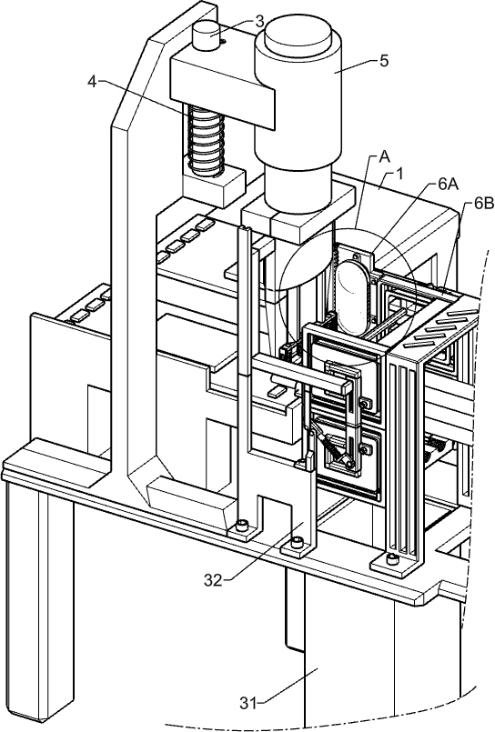
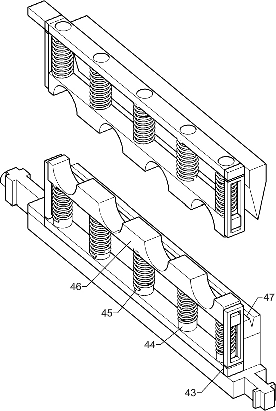
[0030] An automatic IED chip wire bonding device, such as figure 1 , figure 2 , Figure 4 and Figure 5As shown, it includes a processing table 1, a processing frame 2, a processing guide column 3, a processing spring 4, a wire welding machine 5, a square guide rail 6B, a support frame 6A, a terminal block 601, a pay-off table 602, a transmission device, and a motor table 11 , power motor 12 and wire clamping device, processing frame 1 is fixedly connected with processing frame 2, and processing frame 2 is provided with a rectangular gap, wire welding machine 5 is slidably connected on the gap, and processing frame 2 is fixedly connected with processing guide column 3 , the processing guide post 3 is cylindrical, the processing guide post 3 is covered with a processing spring 4, the processing spring 4 provides reset force for the wire bonding machine 5, and the processing guide post 3 is slidably connected with a wire bonding machine 5, and the wire bonding machine 5 It c...
Embodiment 2
[0033] On the basis of Example 1, such as Figure 4 and Figure 7 As shown, the transmission device includes a processing rack 7, a gear cover plate 8, a pulley 9 and a processing belt 10, and a processing rack 7 is slidably connected to the support frame 6A, and the processing rack 7 is fixedly connected with the wire welding machine 5 to support The frame 6A is fixedly connected with a gear cover plate 8, and the gear cover plate 8 is rotationally connected with two symmetrical pulleys 9, the pulley 9 is wound with a processing belt 10, the surface of the processing belt 10 is toothed, and the teeth on the processing belt 10 are connected to the Processing tooth bar 7 engagements, processing tooth bar 7 can drive wire welding machine 5 to descend when processing belt 10 rotates upwards.
[0034] When the clamping device starts to move away from the wire, it will engage with the teeth on the processing belt 10, and drive the processing belt 10 to rotate upwards around the pu...
Embodiment 3
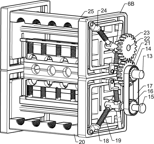
[0036] On the basis of Example 2, such as Figure 5 , Figure 6 and Figure 8 As shown, the clamping device includes a power shaft 13, a belt upper gear 14, a lower shaft 15, a belt lower gear 16, a transmission belt 17, a guide post 18 under a splint, a splint spring 19, a lower splint 20, a power gear 21, and an upper shaft 22, the power upper gear 23, the guide post 24 on the clamping plate, the upper clamping plate 25 and the clamping plate rack 2501, the power rotating shaft 13 is fixedly connected on the rotating shaft of the power motor 12, the power rotating shaft 13 is connected with the motor platform 11 in rotation, and the power rotating shaft 13 is fixed Be connected with belt upper gear 14, can drive belt upper gear 14 to rotate when power rotating shaft 13 rotates, the square guide rail 6B below is rotated and is connected with lower rotating shaft 15, is fixedly connected with belt lower gear 16 on the lower rotating shaft 15, belt upper gear 14 and The belt ...
PUM
 Abstract
Description
Claims
Application Information
 - R&D
- Intellectual Property
- Life Sciences
- Materials
- Tech Scout
- Unparalleled Data Quality
- Higher Quality Content
- 60% Fewer Hallucinations
Browse by: Latest US Patents, China's latest patents, Technical Efficacy Thesaurus, Application Domain, Technology Topic, Popular Technical Reports.
© 2025 PatSnap. All rights reserved.Legal|Privacy policy|Modern Slavery Act Transparency Statement|Sitemap|About US| Contact US: help@patsnap.com


