
Novel looped network metal cabinet

A metal cabinet and ring network technology, which is applied in animal husbandry, dispersed particle filtration, application, etc., can solve the problems of poor protection effect of ring network metal cabinets, reduced service life of the device, external damage to the device, etc., to achieve convenient control operation, uniform The effect of absorbing and reducing the service life

Pending Publication Date: 2022-04-08
ZHEJIANG KELAODE INTELLIGENT EQUIP CO LTD
View PDF0 Cites 0 Cited by
  • Summary
  • Abstract
  • Description
  • Claims
  • Application Information

AI Technical Summary

Problems solved by technology

[0005] The present invention provides a new type of ring network metal cabinet, one of the purposes of which is to solve the problem of poor protection effect of some ring network metal cabinets, corrosion of external rainwater, easy to cause damage to the outside of the device, and reduce the service life of the device; wherein Another purpose is to solve the problem of poor protection effect of some ring network metal cabinets, corrosion of external rainwater, easy to cause damage to the outside of the device, and reduce the service life of the device

Method used


Image

  • Novel looped network metal cabinet
  • Novel looped network metal cabinet
  • Novel looped network metal cabinet

Examples


Embodiment 1

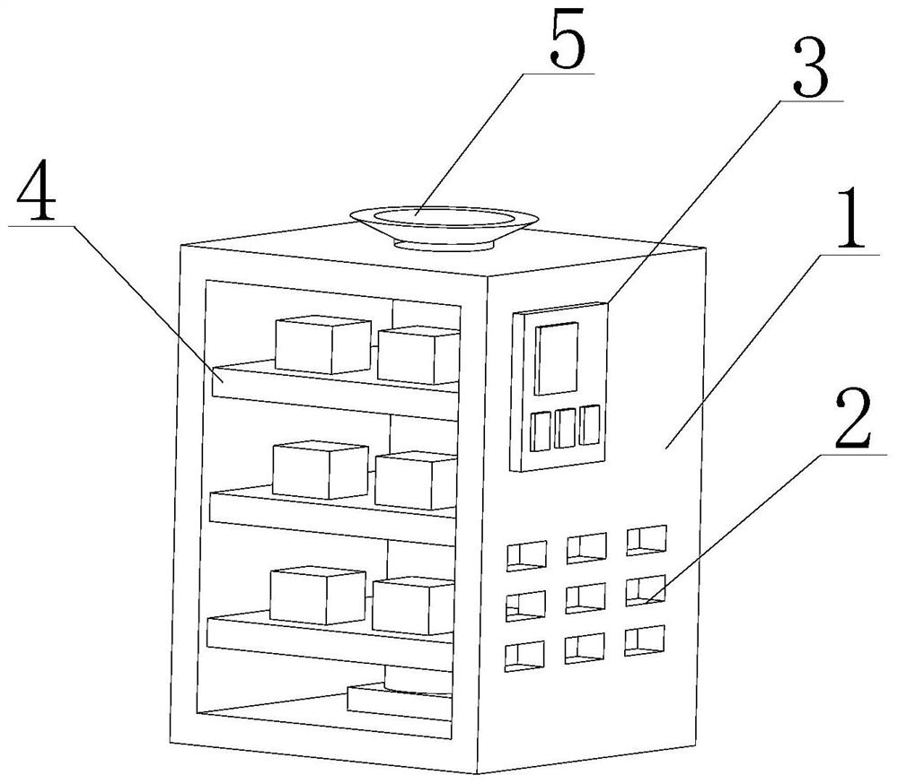
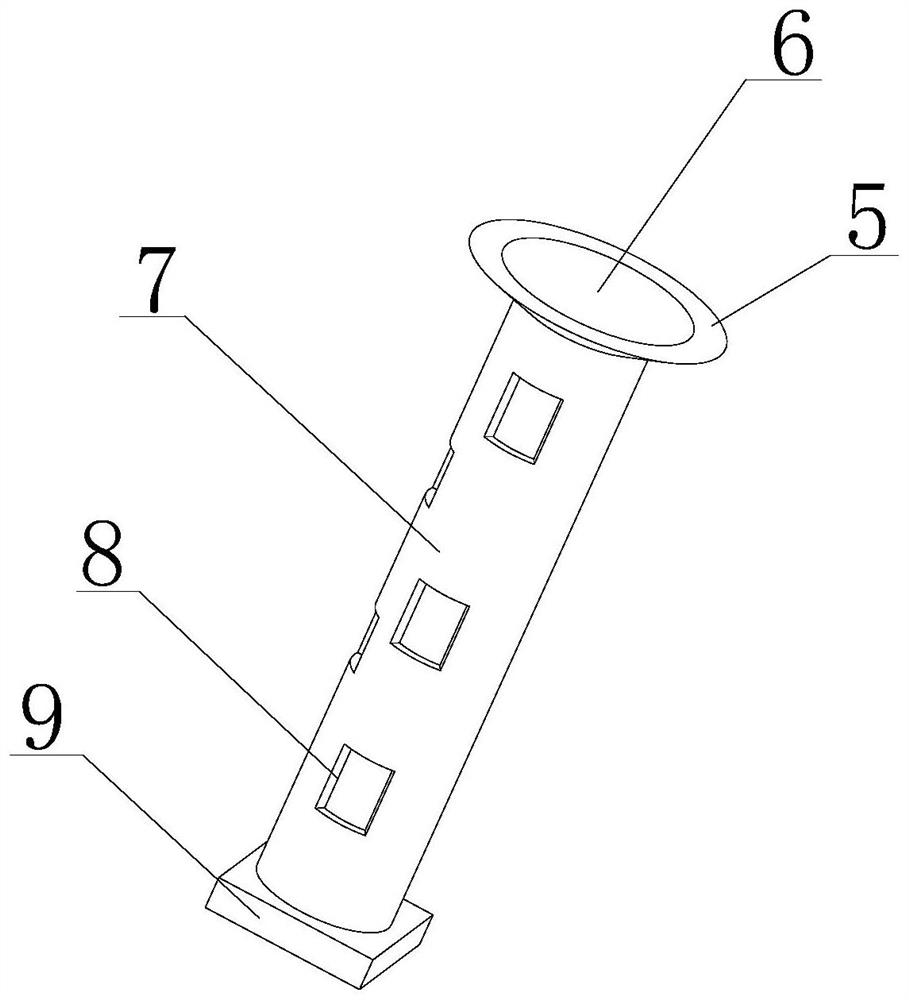
[0029] Such as Figure 1-5 As shown, the present invention provides a novel ring network metal cabinet, comprising a metal cabinet main body 1, a liquid crystal control panel 3 is fixedly connected to the right end of the metal cabinet main body 1, a support frame 4 is arranged inside the metal cabinet main body 1, and the support frame The upper end of 4 is fixedly installed with electronic components, and the support frame 4 and the set electronic components are arranged in three groups, and are evenly distributed in the interior of the metal cabinet main body 1, and the heat dissipation guide tube 7 runs through the three sets of support frames 4, and is arranged on the heat dissipation guide. The heat dissipation ports 8 outside the flow tube 7 are all on the upper ends of the three sets of support frames 4, so that the heat emitted by the three sets of electronic components can be dissipated to effectively improve the efficiency of heat dissipation. The right end of the me...

Embodiment 2

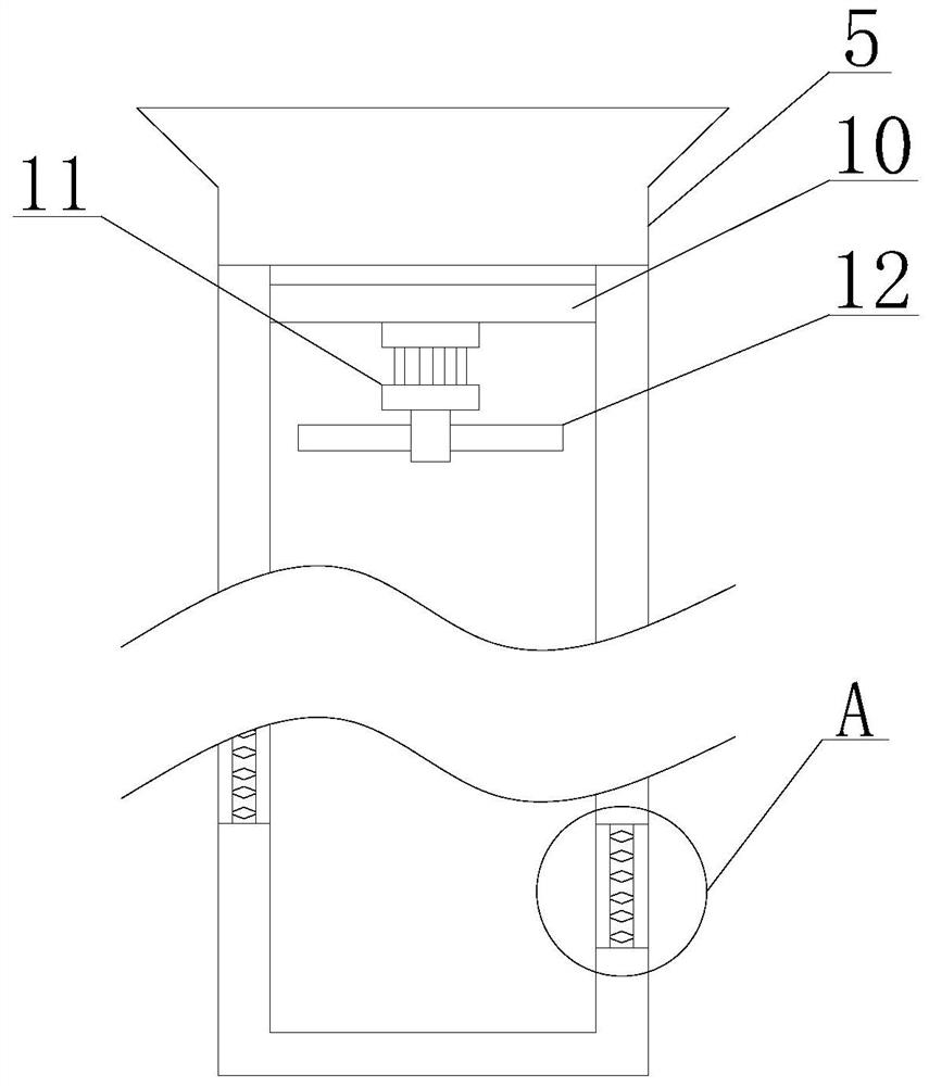
[0032] Such as Figure 1-5As shown, on the basis of Embodiment 1, the present invention provides a technical solution: preferably, the inner bottom end of the metal cabinet main body 1 is fixedly connected with a drive motor 9, and the drive motor 9 is connected to the liquid crystal control panel 3 provided by wires, The setting of the driving motor 9 can drive the heat dissipation duct 7 to rotate, so that the heat inside the device can be evenly absorbed to avoid excessive temperature difference. The lower end of the heat dissipation duct 7 runs through the upper end of the metal cabinet main body 1 provided to dissipate heat The lower end of the guide tube 7 runs through the set support frame 4, and the lower end of the heat dissipation guide tube 7 is movably connected with the upper end of the set drive motor 9. The inside of the metal cabinet main body 1 is fixedly connected with a protective plate 16, and the right end of the protective plate 16 is fixedly connected. T...


PUM


Abstract

The invention discloses a novel looped network metal cabinet, and relates to the technical field of looped network metal cabinets, the novel looped network metal cabinet comprises a metal cabinet main body, the right end of the metal cabinet main body is fixedly connected with a liquid crystal control panel, the metal cabinet main body is internally provided with a support frame, and the upper end of the support frame is fixedly provided with an electronic element; a looped network through hole is formed in the right end of the metal cabinet body in a penetrating mode, an exhaust port is formed in the upper end of the metal cabinet body, and a heat dissipation flow guide pipe is fixedly connected to the lower end of the exhaust port. According to the device, air flow in a heat dissipation flow guide pipe can be driven to move as far as possible through the arrangement of supporting rods and fan blades of a servo motor, then heat in the device can be extracted through the arrangement of a heat dissipation opening, so that the heat dissipation effect can be achieved, in addition, through the arrangement of a filter net plate and a purification net plate, the passing heat can be purified and filtered, and the service life of the device is prolonged. And meanwhile, according to the arrangement of the flow guide element, flowing of airflow can be accelerated, and the flow guide effect is achieved.

Description

technical field [0001] The invention relates to the technical field of ring network metal cabinets, in particular to a novel ring network metal cabinet. Background technique [0002] Switchgear is a power supply control and management equipment often used by industrial enterprises and departments that use three-phase power as power. Although the previous switchgear has the functions of receiving and distributing network power and implementing control, protection and monitoring of circuits. However, it does not yet have the functions of remote control, telemetry, remote signaling and remote adjustment, nor does it have the ability to control the field network through the bus with 485 communication interface, and prevent misoperation of circuit breakers, prevent pushing and pulling handcarts with load, and prevent live closing and grounding switch, prevent the grounding switch from sending power at the grounding position, and prevent stray entry. It cannot meet the needs of s...

Claims


Application Information

Patent Timeline
Patent Type & Authority Applications(China)
IPC IPC(8): H02B13/035H02B1/56H02B1/28B01D46/10A01M29/34
Inventor 罗成国
Owner ZHEJIANG KELAODE INTELLIGENT EQUIP CO LTD
Learn More