Silk thread auxiliary movement device, driving system and control method

A motion device, linear motion technology, applied in medical science, surgical robotics, surgery, etc., can solve the problems of operator inconvenience, complicated device structure, noise artifacts in scanned images, etc., and achieve the effect of increasing accuracy

Pending Publication Date: 2022-04-12
HANGZHOU GENLIGHT MEDTECH CO LTD
View PDF0 Cites 0 Cited by
  • Summary
  • Abstract
  • Description
  • Claims
  • Application Information

AI Technical Summary

Problems solved by technology

[0004] At present, MRgLITT technology is still in the stage of cultivation and development, and the existing surgical assistant robots in similar or other fields still have the following problems, so that they cannot be directly used in this laser ablation: ①, there is no mature one in China The auxiliary tool can not only be used in the magnetic resonance environment, but also can accurately control the movement trajectory of the fiber optic catheter
②, the driving source of the existing surgical auxiliary devices is either manually operated or driven by a driving mechanism
Among them, the disadvantage of manual operation is that the manual control accuracy of the fiber optic catheter can only reach 1 mm, which is far from the control accuracy required for laser ablation surgery (usually less than 0.5 mm); and the manual adjustment method will prolong the operation time , the risk to patients is relatively high
Auxiliary robots with automatic driving mechanisms have more advantages than manual control in terms of precision, but the existing driving mechanisms are generally designed integrally on surgical auxiliary robots. The operation of the driving mechanism will affect the scanning accuracy of MRI and cause noise in the scanned image. Artifacts, etc., bring certain obstacles to the subsequent real-time analysis
③ Considering that the LITT technology is in the early stage of development and application, the orientation control of the fiber optic catheter still needs to "walk on two legs", which can not only achieve the accuracy of manual adjustment to meet the needs of surgery, but also meet the requirements of fully automatic operation in the MRI environment. At present, there is no surgical assistant robot that can be controlled manually and fully automatically, which can realize double precision regulation, so as to meet the needs of high-precision surgery.
④. The existing surgical assisting robots in similar fields have complex structures, large volume and weight. If they are used in laser ablation surgery, additional head frames and holders must be used to fix them, which may lead to On the way into the target area, an additional fixing device is added to limit its running track, and once the positioning of the fixing device is deviated, it will affect the implementation of the clinical operation path, which will cause inconvenience to the operator; and the use of the gripper Easily damaged surgical instruments
⑤. In the existing surgical assistant robots in similar fields, the device structure for realizing linear and / or rotational motion is complicated, which usually requires multiple combination designs between several parts, and the transmission of multiple parts tends to reduce the accuracy of force transmission. Moreover, the device is prone to problems during operation, which greatly reduces the operation stability and reliability of the surgical assistant robot.

Method used


Image

  • Silk thread auxiliary movement device, driving system and control method
  • Silk thread auxiliary movement device, driving system and control method
  • Silk thread auxiliary movement device, driving system and control method

Examples


Embodiment 1

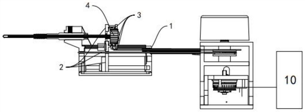
[0069] The present invention proposes an auxiliary movement device including a movement component and a drive component, the movement component and the drive component are arranged separately, and there is a certain distance between the movement component and the drive component in actual use, That is, the drive assembly is set away from the nuclear magnetic body or the magnetic resonance chamber. First, the influence of the drive assembly on magnetic resonance imaging and temperature measurement technology is avoided. Second, the weight of the moving assembly is reduced, so that the volume and weight of the moving assembly Reduced to the minimum, so that the moving component can be fixedly connected with the skull nail without going through an additional fixing device. In addition, the driving device of the driving assembly is preferably an ultrasonic motor to be suitable for use in a nuclear magnetic environment.

[0070] see figure 1 , Figure 2A to Figure 2C , the motion...

Embodiment 2

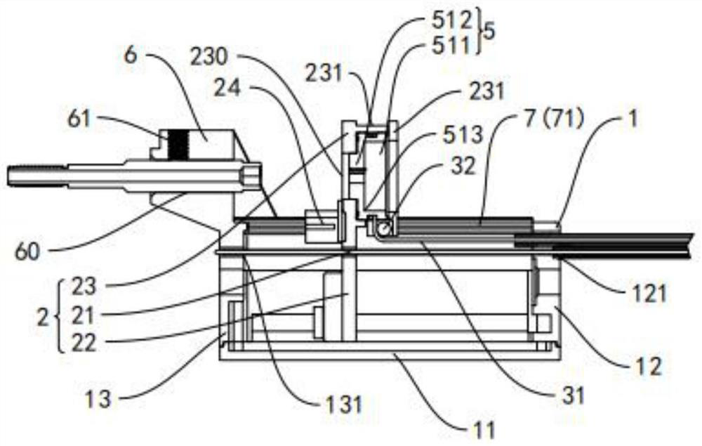
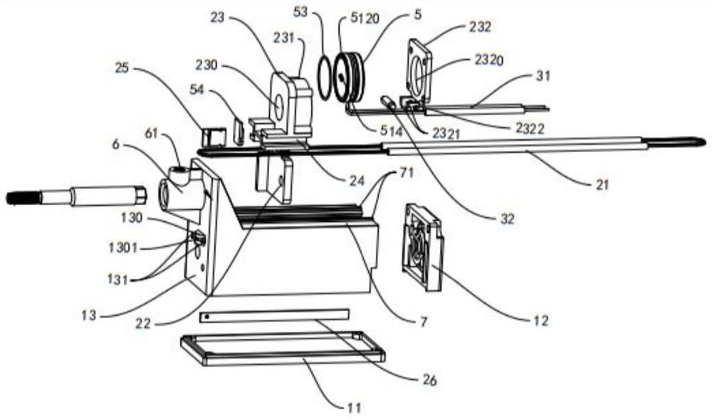
[0085] see Figure 2A to Figure 2C , Figure 4A to Figure 4D , Figure 5 Another specific embodiment 2 of the present invention differs from embodiment 1 in that, in order to make the movement of the rotary motion assembly 3 more stable and precise, the embodiment 2 further improves the fiber catheter fixing part 5 optimized design.

[0086] A perforation 230 is defined on the linear driven moving part 23 , and a ring neck 231 is arranged around the perforation 230 , and the optical fiber catheter fixing part 5 is movably arranged in the ring neck 231 . Preferably, the diameter of the ring neck 231 is larger than the diameter of the perforation 230, and the diameter of the ring neck 231 is slightly larger than the diameter of the fiber catheter fixing part 5, so as to realize that the fiber catheter fixing part 5 is in the ring Rotational movement within the neck 231. In yet another preferred embodiment of the present invention, the fiber catheter fixing portion 5 is a ste...

Embodiment 3

[0094] Further, as Figures 6A-6C As shown, the inside of the ring neck 231 is provided with a fiber optic catheter fixing 5, and the fiber optic catheter fixing 5 includes a fiber optic catheter fixer 51 and a fiber optic catheter fixing member 52, and the fiber optic catheter fixing device 51 and the fiber optic catheter fixing member 52 are detachable Fittingly connected, the fiber optic catheter holder 51 is fixedly fitted inside the ring neck 231 .

[0095] Specifically, the optical fiber catheter fixer 51 is a stepped cavity structure, and the cavity structure includes a first cavity 511 and a second cavity 512 . The first concave cavity 511 and the second concave cavity 512 are both cylindrical concave cavity structures, they are coaxially arranged and adjacent to and communicate with each other, and the diameter of the first concave cavity 511 is larger than that of the second concave cavity 512 The diameter of the two adjacent to form a right-angle boss 513.

[0096...


PUM


Abstract

The invention relates to a silk thread auxiliary movement device, a driving system and a control method, and belongs to the technical field of ablation operation devices. The silk thread auxiliary movement device comprises a rack, a linear movement assembly and a rotary movement assembly, the rotary movement assembly is movably arranged in an annular neck of the linear movement assembly, and the rotary movement assembly is detachably connected with an optical fiber guide pipe; the silk thread auxiliary movement device further comprises a driving assembly, and a linear transmission silk and a rotary transmission silk are wound on the driving assembly. One end of the linear transmission wire is wound on the linear motion assembly, and one end of the rotary transmission wire is wound on the rotary motion assembly; the linear transmission wire is used for driving the linear motion assembly to do linear motion; and the rotary transmission wire is used for driving the rotary motion assembly to do rotary motion. According to the invention, the simultaneous linear motion and rotary motion of the optical fiber conduit are realized, in addition, linear and rotary transmission can be completed by using one motor, and the device structure is simplified.

Description

[0001] The invention relates to the technical field of ablation surgery devices, in particular to a wire auxiliary movement device, a drive system and a control method. Background technique [0002] Medical robotics is a new interdisciplinary research field integrating medicine, biomechanics, mechanics, mechanical mechanics, materials science, computer graphics, computer vision, mathematical analysis, robotics and many other disciplines. It is currently a research hotspot in the field of robotics at home and abroad. . The most commonly used medical robot in the field of neurosurgery is also called surgical robot. In the surgical robot system, auxiliary robots account for nearly 17% of surgical operations and become one of the commonly used auxiliary equipment in daily surgical operations. With the continuous development of technology, surgical robots will develop toward miniaturization, specialization, low cost, intelligence, and automation, and will lead minimally invasive su...

Claims


Application Information

Patent Timeline
IPC IPC(8): A61B34/30A61B18/22
Inventor 金慧杰史鼎盛夏良道于成凯
Owner HANGZHOU GENLIGHT MEDTECH CO LTD
Why Eureka
Try Eureka