
2*2 optical waveguide switch based on phase change material and preparation method thereof

A phase-change material and optical waveguide technology, applied in the field of optoelectronics, can solve the problems of large volume, large insertion loss, limit switch application, etc.

Pending Publication Date: 2022-04-12
SUZHOU UNIV
View PDF0 Cites 3 Cited by
  • Summary
  • Abstract
  • Description
  • Claims
  • Application Information

AI Technical Summary

Problems solved by technology

At present, many common 2×2 optical switches are mechanical, which have large volume, large insertion loss, and unstable optical path switching.
Although the common 2×2 optical switch based on phase-change materials solves these problems, its coupling region is designed based on three-waveguide coupling (see literature: Zhang Q , ZhangY , Li J , et al. Broadband nonvolatile photonic switching based on optical phase change materials: beyond the classical figure-of-merit[J]. OpticsLetters, 2018, 43(1):94.), the phase change material covers the intermediate waveguide, which increases the Experiment difficulty
Also, because the input port of this type of optical switching device currently being studied basically only supports the input of a single transverse electric fundamental mode (TE0) or transverse magnetic fundamental mode (TM0), the mixed mode input of TE0 and TM0 cannot form a switching effect , limiting the application of such switches

Method used


Image

  • 2*2 optical waveguide switch based on phase change material and preparation method thereof
  • 2*2 optical waveguide switch based on phase change material and preparation method thereof
  • 2*2 optical waveguide switch based on phase change material and preparation method thereof

Examples


Embodiment Construction

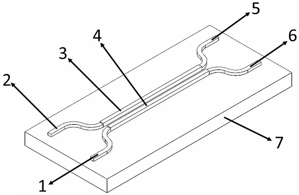
[0024] See attached figure 1 , is a schematic diagram of a phase-change material-based 2×2 optical waveguide switch structure provided in this embodiment. It consists of two axisymmetrically distributed waveguides, including the input port 1, output port 5, covered phase change material 3 of one waveguide and the input port 2, output port 6, covered phase change material of the other waveguide 4.

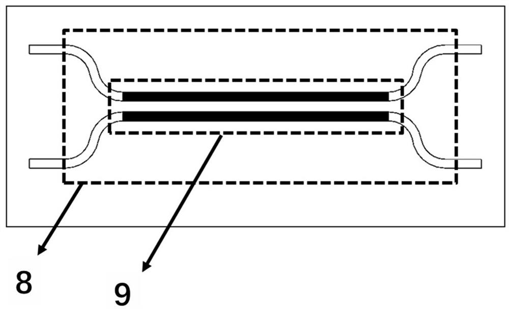
[0025] See attached figure 2 , is a top view of the phase-change material-based 2×2 optical waveguide switch structure provided in this embodiment. The switch area 8, the dotted box is the coupling area 2 covered with the phase change material. Depending on the input port, it can be changed by changing figure 1 The phase state of the phase change materials 3 and 4 is used to change the output port of the optical signal.

[0026] In the technical solution of the present invention, the coupling length of the waveguide can be accurately calculated by the supermode coupling theory...


PUM

PropertyMeasurementUnit
Thicknessaaaaaaaaaa

Abstract

The invention discloses a phase change material-based 2 * 2 optical waveguide switch and a preparation method thereof. A 2 * 2 optical switch unit waveguide structure is arranged on a substrate, two waveguides are distributed in an axial symmetry mode and comprise two input ports and two output ports, and a coupling area is arranged between the two waveguides; and a uniform hundred-nanoscale Ge2Sb2Se4Te1 thin film consistent with the components of the target material is prepared in a coupling region by adopting a pulse laser deposition method. The switch unit is controlled by the phase change material covering the waveguide in the coupling area, the phase state of the phase change material is switched to complete the functions of dual-channel selection input, dual-channel gating and mode switching for the transverse electric fundamental mode, and the function of same-side port input and same-side port output for the transverse magnetic fundamental mode is met. The invention has the characteristics of high extinction ratio, small size and high switching speed.

Description

technical field [0001] The invention belongs to the technical field of optoelectronics, and in particular relates to a 2×2 optical waveguide switch based on a phase change material and a preparation method thereof. Background technique [0002] With the development of technologies such as virtual reality, augmented display, cloud computing, big data, and artificial intelligence, higher requirements are placed on communication capacity, and finding new multiplexing technologies has become a new research hotspot in the field of optical communication. The use of spatial dimension as a new resource for information bearing has brought new changes to network technology. The multiplexing of spatial dimension increases the physical dimension and information capacity of communication networks. It is a multiplexing technology that needs to be developed and utilized urgently. Spatial mode multiplexing, referred to as "mode division multiplexing", is a kind of spatial dimension multiple...

Claims


Application Information

Patent Timeline
IPC IPC(8): G02F1/01G02B6/13
Inventor 张桂菊汪成根王笑笑
Owner SUZHOU UNIV
Learn More