

Environment-friendly recycling process for waste wires and cables for electric power engineering
A technology for waste wires and electric power engineering, which is applied in the field of environmental protection recycling technology for waste wires and cables used in power engineering, can solve the problems of low production efficiency, environmental protection, high labor costs, etc., and achieve simple structure, easy adjustment, and improved use efficiency Effect
- Summary
- Abstract
- Description
- Claims
- Application Information
AI Technical Summary
Problems solved by technology
Method used
Image

Examples
Embodiment Construction
[0047] The following will clearly and completely describe the technical solutions in the embodiments of the present invention with reference to the accompanying drawings in the embodiments of the present invention. Obviously, the described embodiments are only some, not all, embodiments of the present invention. Based on the embodiments of the present invention, all other embodiments obtained by persons of ordinary skill in the art without making creative efforts belong to the protection scope of the present invention.
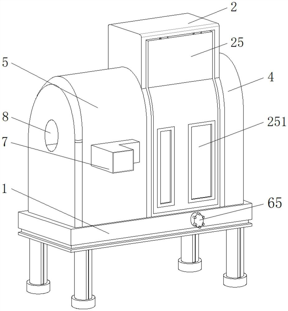
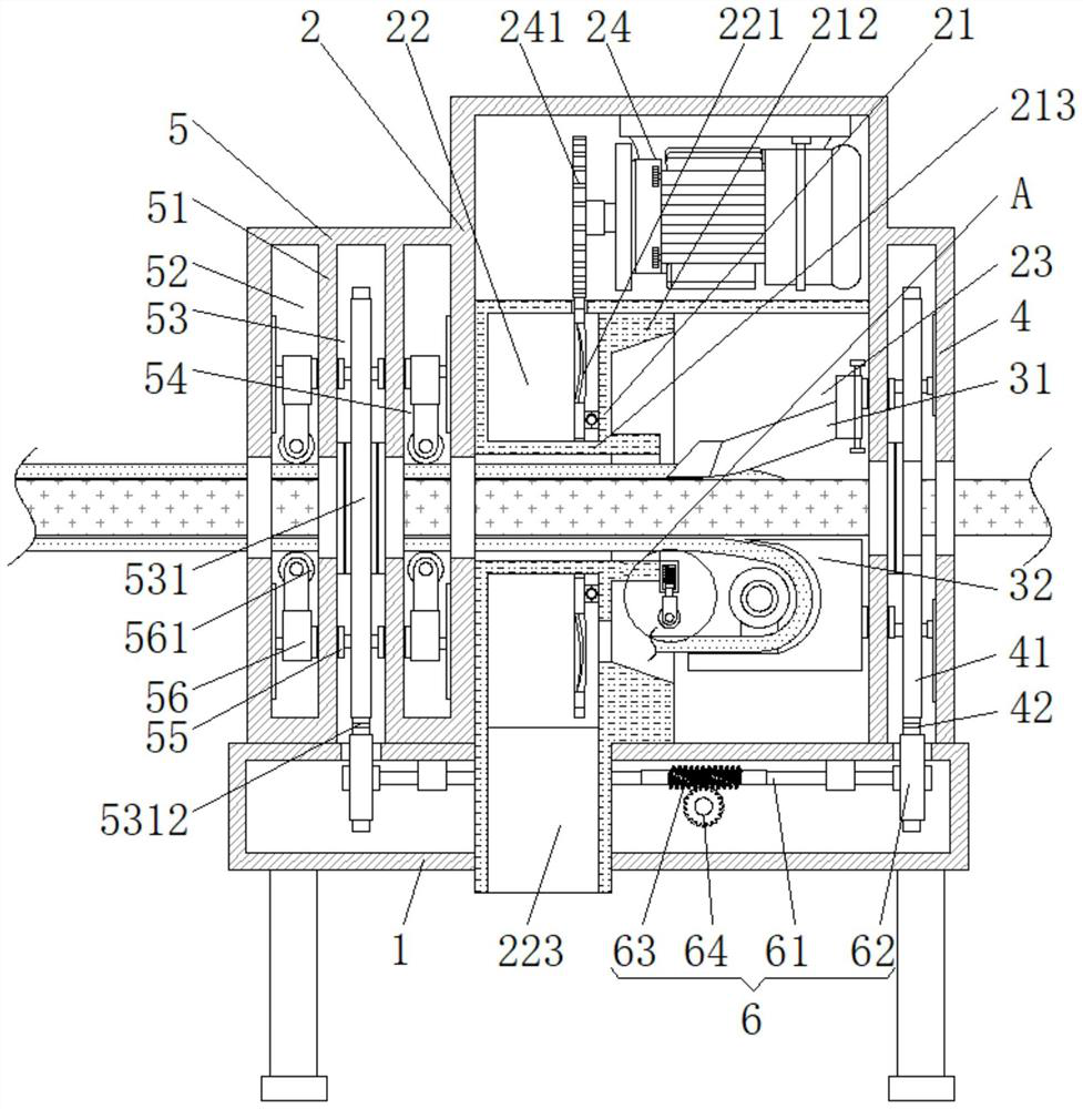
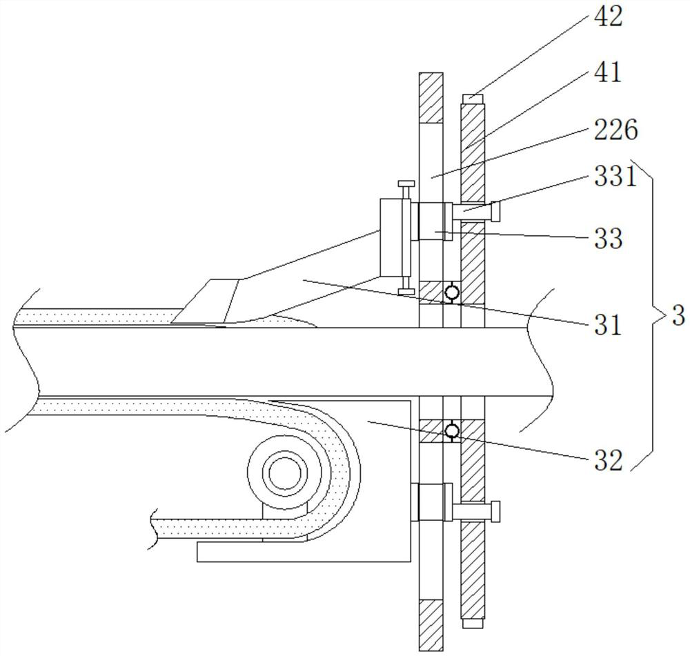
[0048] see Figure 1-9 , the present invention provides a technical solution: an environmentally friendly recovery process for waste wires and cables used in electric power engineering, specifically comprising the following steps:
[0049] Step 1. Collect and arrange the waste electric wires so that they can pass through the entrance of the waste electric wire recovery treatment device;
[0050] Step 2. Put the old electric wires at the entrance of the waste ...
PUM
 Abstract
Description
Claims
Application Information