
Photocatalytic hydrogen production catalyst as well as preparation method and application thereof

A catalyst and photocatalysis technology, applied in the field of materials, can solve problems such as low catalytic yield, achieve the effect of small change in hydrogen evolution rate, promote separation and isolation of photogenerated charge carriers, and improve photocatalytic hydrogen production activity

Pending Publication Date: 2022-04-15
湖南声海电子有限公司
View PDF0 Cites 0 Cited by
  • Summary
  • Abstract
  • Description
  • Claims
  • Application Information

AI Technical Summary

Problems solved by technology

However, the existing photocatalysts generally have the problem of low catalytic yield when catalyzing water to produce hydrogen.

Method used


Image

  • Photocatalytic hydrogen production catalyst as well as preparation method and application thereof
  • Photocatalytic hydrogen production catalyst as well as preparation method and application thereof
  • Photocatalytic hydrogen production catalyst as well as preparation method and application thereof

Examples


Embodiment 1

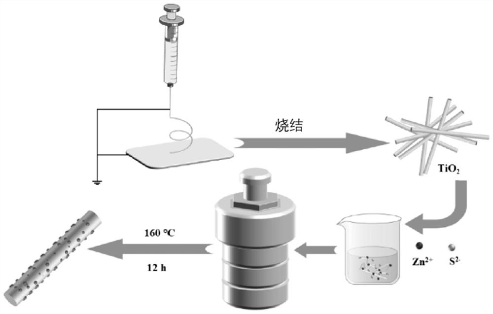
[0066] The preparation method of the photocatalytic hydrogen production catalyst in this example is as follows:

[0067] (1) TiO 2 preparation:

[0068] Dissolve 0.45g of polyvinylpyrrolidone (PVP), 3mL of glacial acetic acid and 1.5g of tetrabutyl titanate in 3mL of methanol to form a mixed solution, and stir the mixed solution at room temperature (25°C) for 12 hours to obtain a clear solution; transfer the solution In the injection device, electrospinning is carried out afterwards. The voltage of electrospinning is 18kV, the feed rate is 0.5ml / h, and the height of the electrospinning needle nozzle from the collector is 14cm; the nanofibers formed after electrospinning Transfer to a crucible and sinter in a muffle furnace to remove excess polyvinylpyrrolidone and other organic components. The sintering temperature in the muffle furnace was 550°C for 2 hours, and the heating rate of the muffle furnace was 1°C / min; after 2 hours, the crucible was quickly taken out and cooled ...

Embodiment 2

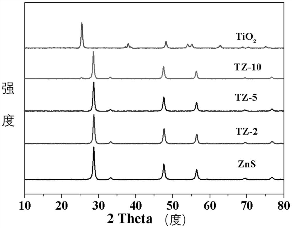
[0074] The photocatalytic hydrogen production catalyst in this example is prepared with reference to the photocatalytic preparation method in Example 1, and the TiO in the photocatalytic hydrogen production catalyst in this example 2 The mass ratio to ZnS is 2:1, which is recorded as TZ-2.

Embodiment 3

[0076] The photocatalytic hydrogen production catalyst in this example is prepared with reference to the photocatalytic preparation method in Example 1, and the TiO in the photocatalytic hydrogen production catalyst in this example 2 The mass ratio to ZnS is 10:1, which is recorded as TZ-10.

[0077] The preparation roadmap of the photocatalytic hydrogen production catalyst in Examples 1 to 3 is shown in figure 1 shown.


PUM


Abstract

The invention discloses a photocatalytic hydrogen production catalyst and a preparation method and application thereof, the catalyst has a porous structure, and the catalyst comprises titanium dioxide nanofiber and zinc sulfide; zinc sulfide nanoparticles are loaded on the titanium dioxide nanofibers in situ; an S-shaped heterojunction structure is formed between the titanium dioxide nanofiber and the zinc sulfide nanoparticles. An S-shaped heterojunction structure is formed between the titanium dioxide nanofibers and the zinc sulfide nanoparticles in the photocatalytic hydrogen production catalyst, separation of electron holes and the effect of isolating photo-generated charge carriers can be promoted, so that the photocatalytic hydrogen production activity is improved, and when the photocatalytic hydrogen production catalyst is applied to photocatalytic hydrogen production, the hydrogen evolution rate exceeds 2400 [mu] mol.g <-1 > h <-1 >. In addition, the photocatalytic hydrogen production catalyst has high stability and can be recycled, and the change of the hydrogen evolution rate of the photocatalytic hydrogen production catalyst is small when the photocatalytic hydrogen production catalyst is recycled.

Description

technical field [0001] The invention belongs to the field of materials, and in particular relates to a photocatalytic hydrogen production catalyst and its preparation method and application. Background technique [0002] Hydrogen energy is the chemical energy of hydrogen. Hydrogen mainly appears in the form of compound state on the earth. It is the most widely distributed substance in the universe, and it constitutes 75% of the mass of the universe. There are many ways to produce hydrogen in industry, common ones are water electrolysis hydrogen production, coal gasification hydrogen production, heavy oil and natural gas steam catalytic conversion hydrogen production, etc., but the energy consumed by these reactions is greater than the energy produced by them. high. At present, photocatalytic hydrogen production from water is a new method, which generates hydrogen through photocatalytic decomposition of water. This technology has the advantages of low cost, stable chemical p...

Claims


Application Information

Patent Timeline
IPC IPC(8): B01J27/04B01J35/10C01B3/04
Inventor 陈革文周宝峰肖宇彬苏耀荣莫钧达
Owner 湖南声海电子有限公司
Learn More