
Gene detection equipment

A gene detection and equipment technology, applied in biochemical equipment and methods, microbial measurement/inspection, biomass post-processing, etc., can solve the problems of increasing equipment volume, large space occupied by partition room isolation, and difficulty in arranging transfer devices , to achieve the effect of avoiding cross-contamination and high-efficiency genetic testing

Active Publication Date: 2022-04-15
HC BIOENG (CHENGDU) CO LTD
View PDF14 Cites 0 Cited by
  • Summary
  • Abstract
  • Description
  • Claims
  • Application Information

AI Technical Summary

Problems solved by technology

In this way, it is necessary to arrange test personnel in the middle of each partition room, without realizing automation, the efficiency is not high, and the isolation of partition rooms occupies a large space and the cost is very high
[0006] When designing a large-scale PCR laboratory as an integrated nucleic acid extraction and detection device, in order to prevent cross-contamination, it is often chosen to set the gradient air pressure and buffer area of ​​each working area to avoid cross-contamination. However, if multiple In the buffer room, it is necessary to disperse the transfer devices for multiple PCR plates, which will inevitably increase the volume of the equipment, and it is difficult to arrange multiple transfer devices; if only one buffer room is installed, it exists as the intermediate value of the gradient pressure, although it can ensure high pressure work. The area can avoid external pollution, and the low-pressure work area can avoid polluting the outside world, but it cannot prevent air from flowing from the high-pressure work area to the low-pressure work area through the buffer room, and air cross-contamination still occurs

Method used


Image

  • Gene detection equipment
  • Gene detection equipment
  • Gene detection equipment

Examples


Embodiment Construction

[0061] In order to make the purpose, technical solutions and advantages of the embodiments of the present invention more clear, the technical solutions in the embodiments of the present invention will be clearly and completely described below in conjunction with the drawings in the embodiments of the present invention. Apparently, the described embodiments are some, but not all, embodiments of the present invention. The components of the embodiments of the invention generally described and illustrated in the figures herein may be arranged and designed in a variety of different configurations.

[0062] Accordingly, the following detailed description of the embodiments of the invention provided in the accompanying drawings is not intended to limit the scope of the claimed invention, but merely represents selected embodiments of the invention. Based on the embodiments of the present invention, all other embodiments obtained by persons of ordinary skill in the art without creative...


PUM


Abstract

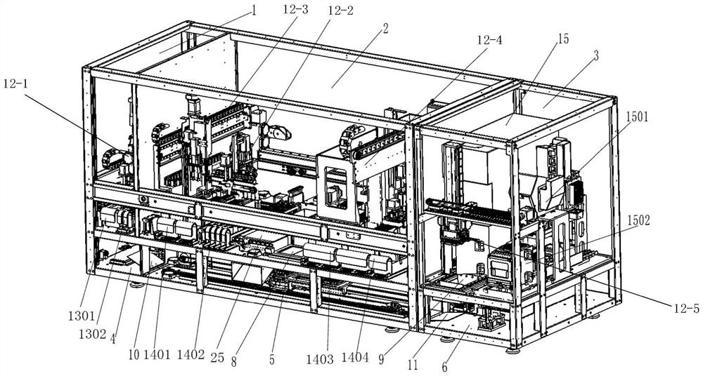
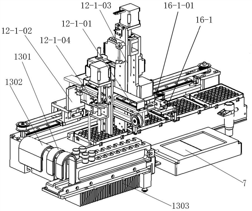
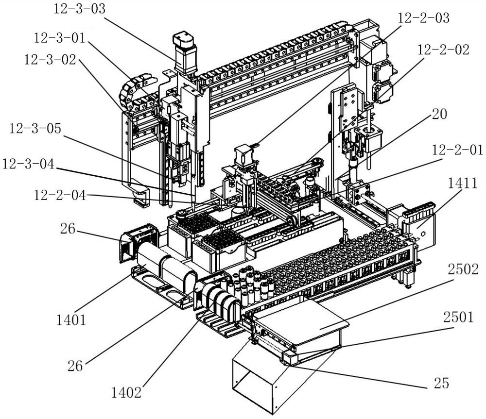
The invention discloses gene detection equipment, and relates to the field of gene detection.The gene detection equipment comprises a safety cabinet, the safety cabinet comprises an upper-layer cabinet body and a lower-layer cabinet body, the upper-layer cabinet body is used for processing and detecting gene samples, and the lower-layer cabinet body is used for transporting PCR plates; three mutually independent mounting chambers are arranged in the upper-layer cabinet body, three mounting chambers are arranged in the lower-layer cabinet body, and door opening and closing assemblies are arranged between each mounting chamber of the upper-layer cabinet body and the corresponding mounting chamber of the lower-layer cabinet body and between the adjacent mounting chambers of the lower-layer cabinet body; an airflow control system is arranged in the upper-layer mounting chamber and is used for controlling the air pressure conditions of the three upper-layer mounting chambers, so that the air pressures of the three mounting chambers are sequentially reduced. By means of the gene detection equipment, automatic and efficient gene detection is achieved, pollution-free transfer of gene samples from sample adding and purification to amplification detection is guaranteed, and cross contamination is avoided.

Description

[0001] The parent filing date of this divisional application is October 19, 2020, the application number is 202011116049.5, and the invention name is "genetic testing equipment". technical field [0002] The invention relates to the field of gene detection, in particular to a gene detection device. Background technique [0003] Genetic testing refers to the analysis of the base sequence of a specific DNA fragment, that is, the arrangement of adenine, thymine, cytosine and guanine; a gene is the basic unit of inheritance, a DNA or RNA sequence carrying genetic information, through replication, the The genetic information is passed on to the next generation, directing the synthesis of proteins to express the genetic information it carries, thereby controlling the expression of the traits of individual organisms. Genetic testing is a technology for detecting DNA through blood, other body fluids, or cells. It is to take the peripheral venous blood or other tissue cells of the te...

Claims


Application Information

Patent Timeline
Patent Type & Authority Applications(China)
IPC IPC(8): C12M1/36C12M1/34C12M1/12C12M1/08C12M1/00
CPCC12Q1/686C12Q2563/143C12Q2563/149C12M1/08C12M1/36C12M1/34C12M1/12C12M1/00C12M1/24C12M1/42Y02A90/10B01L7/52B01L2300/087G01N2035/00346G01N35/02G01N2035/00306G01N2035/0415
Inventor 陈健周德江李杰
Owner HC BIOENG (CHENGDU) CO LTD
Learn More