
Carbon fiber composite material for new energy automobile chassis structure and battery pack tray

A technology for new energy vehicles and composite materials, applied in the field of carbon fiber composite materials, can solve problems such as inability to meet the requirements and the battery pack cover does not have thermal insulation, and achieve the effect of reducing the production process.

Inactive Publication Date: 2022-04-19
浙江阿莱西澳智能装备科技有限公司
View PDF8 Cites 1 Cited by
  • Summary
  • Abstract
  • Description
  • Claims
  • Application Information

AI Technical Summary

Problems solved by technology

Under the premise of guaranteeing the strength, the requirements for the lightweight of the whole vehicle continue to increase, which cannot meet the market demand
Taking the battery pack tray with aluminum alloy structure as an example, all new energy battery packs are combined with aluminum alloy tray CNC processing and engineering plastic injection molding battery cover. The battery pack cover is not only heavy but also has no heat insulation function.

Method used


Image

  • Carbon fiber composite material for new energy automobile chassis structure and battery pack tray
  • Carbon fiber composite material for new energy automobile chassis structure and battery pack tray
  • Carbon fiber composite material for new energy automobile chassis structure and battery pack tray

Examples


preparation example Construction

[0036] The present invention also relates to a method for preparing the carbon fiber composite material, comprising the following steps:

[0037] (1) Preparation of carbon fiber and first resin material to obtain thermoplastic carbon fiber unidirectional tape;

[0038] In one embodiment of the present invention, in parts by weight, the carbon fiber is 50-65 parts, and the first resin material is 35-50 parts.

[0039] In one embodiment of the present invention, the first resin material is PET or PPO. The aforementioned resin material and the underlying inner core material are preferably the same material, which facilitates subsequent thermoforming. This step is carried out using a continuous compound press line.

[0040] Such as figure 2 As shown, this process is carried out by the continuous compound press production line known in the art, and this production line comprises the yarn rack 2-1, extruder 2-2, yarn spreading device 2-3, dipping die head 2- 4. Cooling and sett...

Embodiment 1

[0057] A carbon fiber composite material used for a chassis structure of a new energy vehicle and a battery pack tray, the preparation method of which comprises the following steps:

[0058] (1) A continuous composite press production line is used to prepare a thermoplastic carbon fiber unidirectional tape from carbon fiber and the first resin material PET, wherein the carbon fiber is 65 parts and the first resin material is 35 parts.

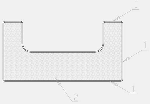
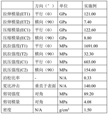
[0059] (2) Adding a chain extender to the second resin material PET for modification, the chain extender is 1,4-butanediol (BDO), and the added amount is 5% by mass of the second resin material. Then pelletizing and carbon dioxide supercritical physical foaming are carried out to obtain beads. EPET beads are added to the beads, the mass ratio of the second resin material to the EPET beads is 5:3, and a structural part of any shape is formed by a fully automatic molding machine to obtain the inner carbon fiber composite material. core. Compres...


PUM

PropertyMeasurementUnit
thicknessaaaaaaaaaa
thicknessaaaaaaaaaa

Abstract

The invention provides a carbon fiber composite material for a new energy automobile chassis structure and a battery pack tray, which is formed by adopting carbon fiber composite foaming high-flame-retardant (UL94V-0) EPET / EPPO, has a sandwich structure, and can realize multiple effects of overall heat preservation, heat insulation and weight reduction of a battery pack. Specifically, the composite material can replace a metal vehicle body structure chassis to realize the functions of light weight and high strength, has an overall heat preservation and heat insulation function on a battery pack, and also can reduce the weight of a battery pack cover plate, so that the production process can be greatly reduced.

Description

technical field [0001] The invention relates to the technical field of carbon fiber materials, in particular to a carbon fiber composite material used for chassis structures and battery pack trays of new energy vehicles. Background technique [0002] At present, the global new energy vehicle chassis adopts the following structural types: steel structure, aluminum alloy structure or aluminum-magnesium alloy structure. Under the premise of guaranteeing the strength, the requirements for reducing the weight of the whole vehicle are constantly increasing, which cannot meet the market demand. Taking the battery pack tray with aluminum alloy structure as an example, all new energy battery packs are combined with aluminum alloy tray CNC processing and engineering plastic injection molding battery cover. The battery pack cover is not only heavy but also has no heat insulation function. [0003] Therefore, it is necessary to improve the above structure so that the chassis structure ...

Claims


Application Information

Patent Timeline
Patent Type & Authority Applications(China)
IPC IPC(8): H01M50/231H01M50/229H01M50/244H01M50/249H01M10/625H01M10/658B29C69/00B29C70/50B29C70/70B29B11/12B29B11/14B29K67/00B29K71/00B29K77/00
CPCH01M50/249H01M10/625H01M10/658B29C69/00B29C70/506B29C70/70B29B11/12B29B11/14B29K2067/003B29K2071/12B29K2071/00B29K2077/00H01M50/282H01M50/28H01M50/278H01M50/276H01M10/615B60R13/08B62D25/20B60L50/64B29C49/071B29C2949/0715Y02E60/10
Inventor 陆炜
Owner 浙江阿莱西澳智能装备科技有限公司
Learn More