Split-flow recompression pure oxygen combustion circulation system

A circulating system and recompression technology, applied in combustion engines, internal combustion piston engines, steam engines, etc., can solve the problems of system efficiency, large heat loss, and high cost

Active Publication Date: 2022-04-22
TSINGHUA UNIV
View PDF5 Cites 2 Cited by
  • Summary
  • Abstract
  • Description
  • Claims
  • Application Information

AI Technical Summary

Problems solved by technology

[0002] Although the existing coal-fired power plants and gas-steam combined cycle power plants can guarantee a stable power supply, the cycle power generation systems of the above-mentioned power plants generally use air as a combustion aid. 2 There are other types of gases, such as nitrogen, etc., so when carbon capture, storage and utilization measures are used for decarbonization, the process is complicated, which has a great impact on system efficiency and high cost
[0003] On the other hand, in the traditional gas-steam combined cycle power generation system, the working fluid flowing in the top cycle (gas power generation) and the working fluid flowing in the bottom cycle (steam power generation) are usually operated separately, only at the waste heat boiler Carry out heat exchange, in this case, the heat exchange loss is relatively large, and the energy utilization efficiency is low

Method used


Image

  • Split-flow recompression pure oxygen combustion circulation system
  • Split-flow recompression pure oxygen combustion circulation system

Examples


no. 1 approach

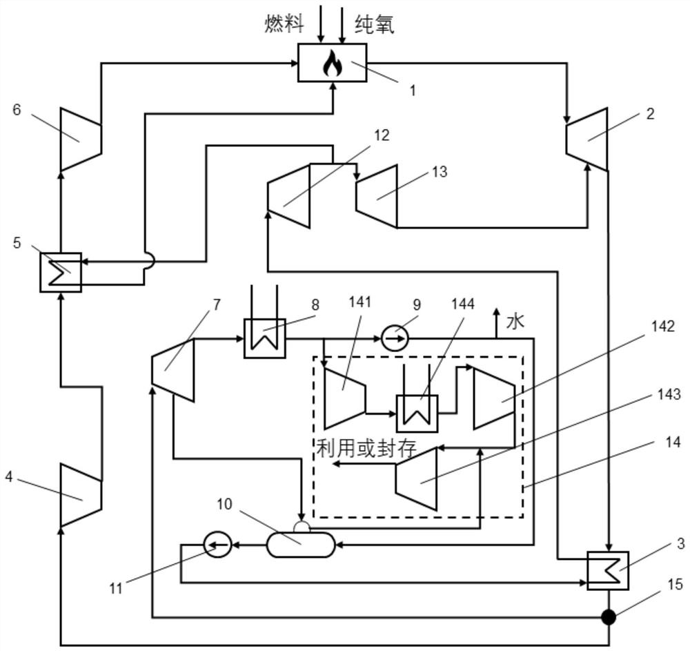
[0056] The split flow recompression pure oxygen combustion cycle system of this embodiment can be applied to the case where the fuel is hydrocarbon. Such as figure 1As shown, the combustion chamber 1, the gas turbine 2, the waste heat boiler 3, the splitter device 15, the first low-pressure compressor 4 and the first high-pressure compressor 6 are sequentially connected in series to form a flow path for the circulation of the working medium, and the flow path can be In a semi-closed circuit, the low-pressure steam turbine 7, condenser 8, condensate pump 9, deaerator 10 and feed water pump 11 are sequentially connected in series to form a flow path for gas-liquid separation.

[0057] Specifically, the outlet side of the combustion chamber 1 is connected to the high-temperature inlet side of the gas turbine 2 , the low-temperature outlet side of the gas turbine 2 is connected to the hot-end inlet side of the waste heat boiler 3 , and the hot-end outlet side of the waste heat boi...

no. 2 approach

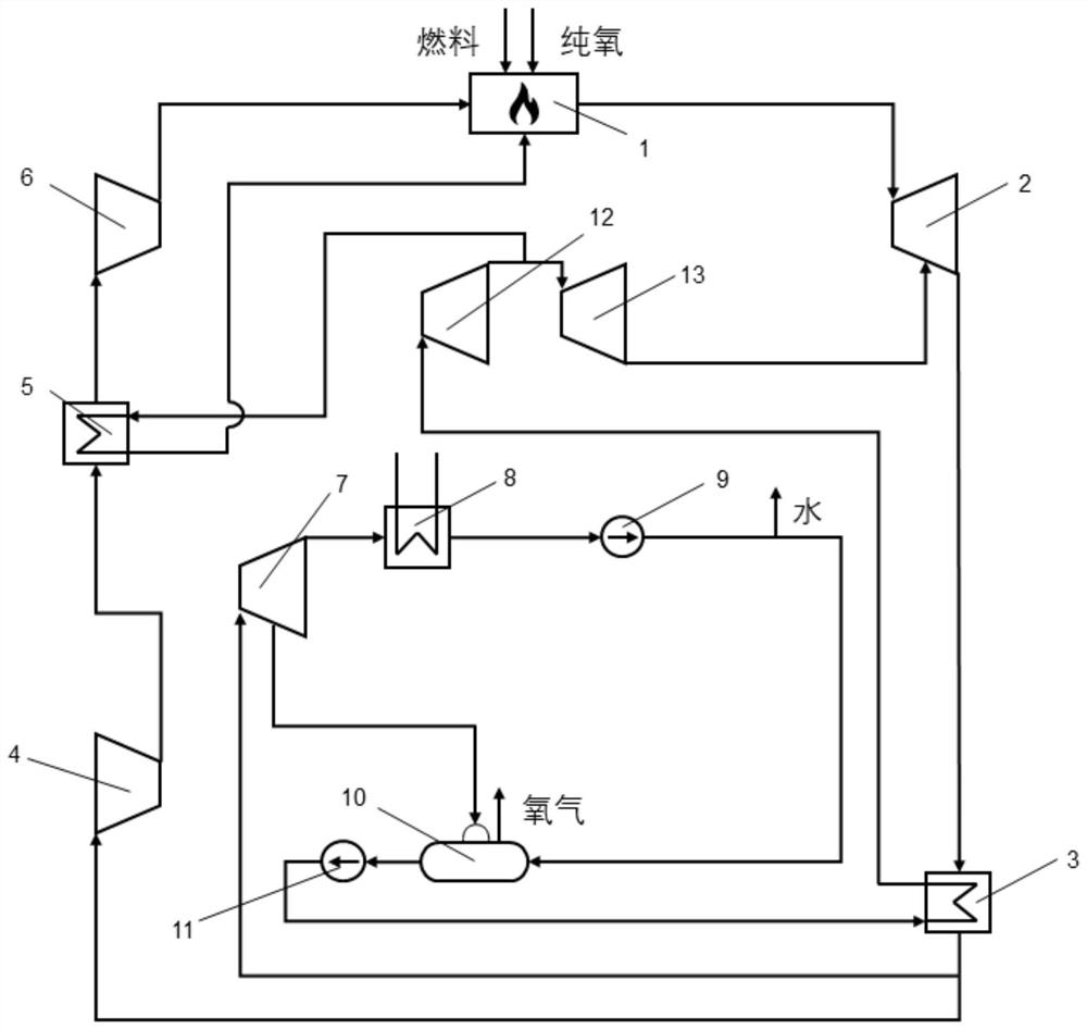
[0079] figure 2 A split-flow recompression oxy-combustion cycle system according to a second embodiment of the present application is shown. The same or similar reference numerals are assigned to the same or similar components as those of the first embodiment, and detailed descriptions of these components are omitted.

[0080] The split flow recompression pure oxygen combustion cycle system of this embodiment can be applied to the case where the fuel is hydrogen. Such as figure 2 As shown, the difference with the first embodiment is: (1) Since the combustion product of hydrogen and oxygen is water vapor, not doped with carbon dioxide, the circulation system of this embodiment does not include a carbon dioxide capture system 14; (2 ) Since there is no need to adjust the working medium ratio of each branch according to the hydrocarbon ratio of the hydrocarbon, the flow splitting device 15 equipped with a proportional regulating valve is not provided, as long as the gas working...


PUM


Abstract

According to the split-flow recompression pure oxygen combustion circulation system with pure oxygen as the combustion improver, a combustion chamber, a gas turbine, a waste heat boiler, a first low-pressure compressor, a first intercooler and a first high-pressure compressor are sequentially connected in series, and a low-pressure steam turbine, a condenser, a condensate pump, a deaerator and a water feeding pump are sequentially connected in series. The hot end outlet side of the waste heat boiler is connected with the high-temperature inlet side of the low-pressure steam turbine and the inlet side of the first low-pressure compressor, so that working media flowing out of the hot end outlet side of the waste heat boiler are divided, and the liquid outlet side of the water feeding pump is connected with the cold end inlet side of the waste heat boiler. A high-pressure steam turbine is arranged between the cold end outlet side of the waste heat boiler and the inlet side of the combustion chamber, the low-temperature outlet side of the high-pressure steam turbine is connected with the cold end inlet side of a first intercooler and a gas turbine, and the cold end outlet side of the first intercooler is connected with the inlet side of the combustion chamber. The hot end inlet side is connected with the outlet side of the first low-pressure compressor, and the hot end outlet side is connected with the inlet side of the first high-pressure compressor.

Description

technical field [0001] This application relates to the field of cycle power generation, and in particular to technical equipment for controlling greenhouse gas emissions, carbon emission reduction technical equipment, carbon capture and carbon sequestration technology and utilization systems. Combustion cycle system. Background technique [0002] Although the existing coal-fired power plants and gas-steam combined cycle power plants can guarantee a stable power supply, the cycle power generation systems of the above-mentioned power plants generally use air as a combustion aid. 2 There are other types of gases, such as nitrogen, etc. Therefore, the process of decarbonization using carbon capture, storage and utilization measures is complicated, which has a great impact on system efficiency and high cost. [0003] On the other hand, in the traditional gas-steam combined cycle power generation system, the working fluid flowing in the top cycle (gas power generation) and the ...

Claims


Application Information

Patent Timeline
Patent Type & Authority Applications(China)
IPC IPC(8): F01K21/04F01K9/00F02B29/04
CPCF01K21/04F01K9/00F02B29/0406Y02T10/12Y02E20/16
Inventor 任晓栋胡博李雪松顾春伟余世达
Owner TSINGHUA UNIV
Why Eureka
Try Eureka