Waste gas treatment equipment for waste incineration
A waste gas treatment equipment, waste gas treatment technology, applied in separation methods, transportation and packaging, dispersed particle separation, etc., to achieve the effect of improving the effect, reducing the damage, and improving the utilization rate
- Summary
- Abstract
- Description
- Claims
- Application Information
AI Technical Summary
Problems solved by technology
Method used
Image

Examples
Embodiment 1
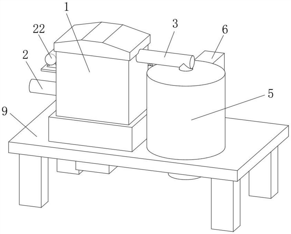
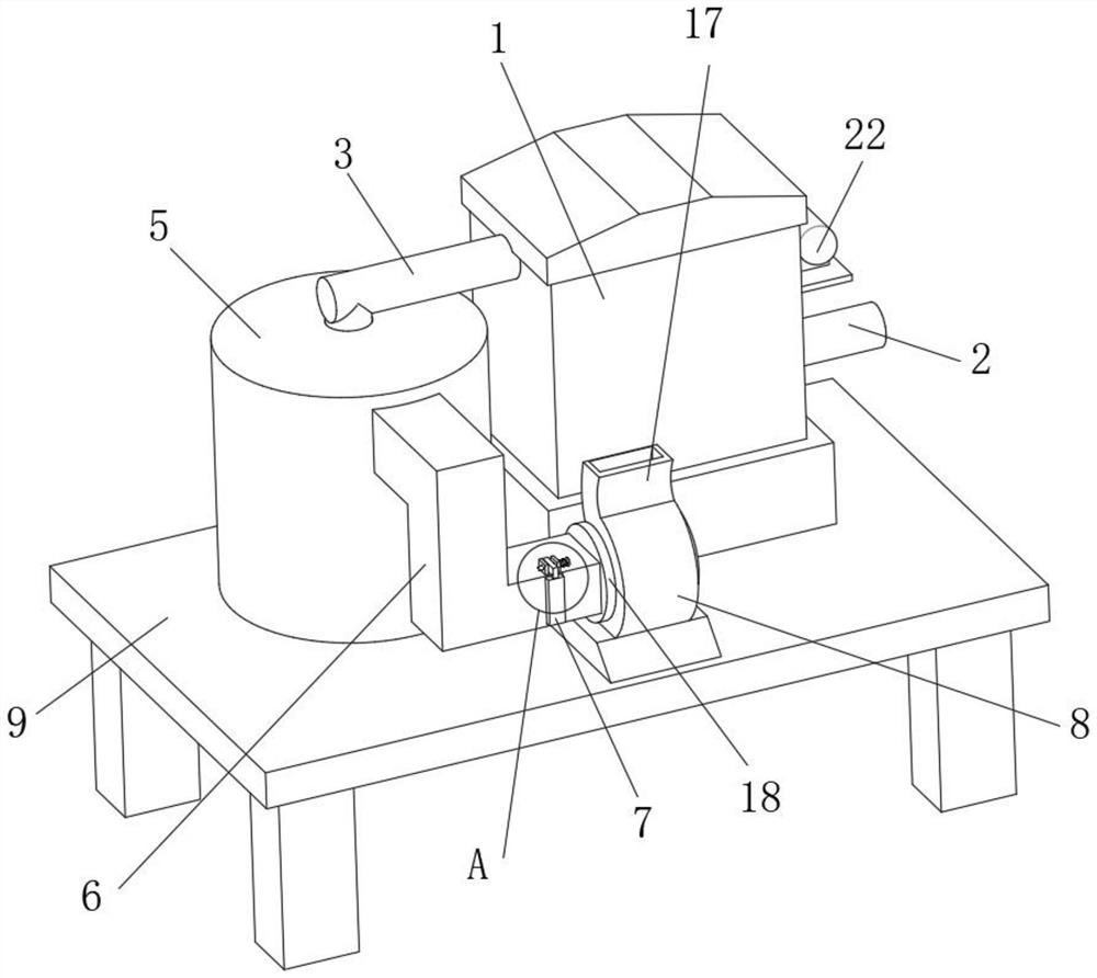
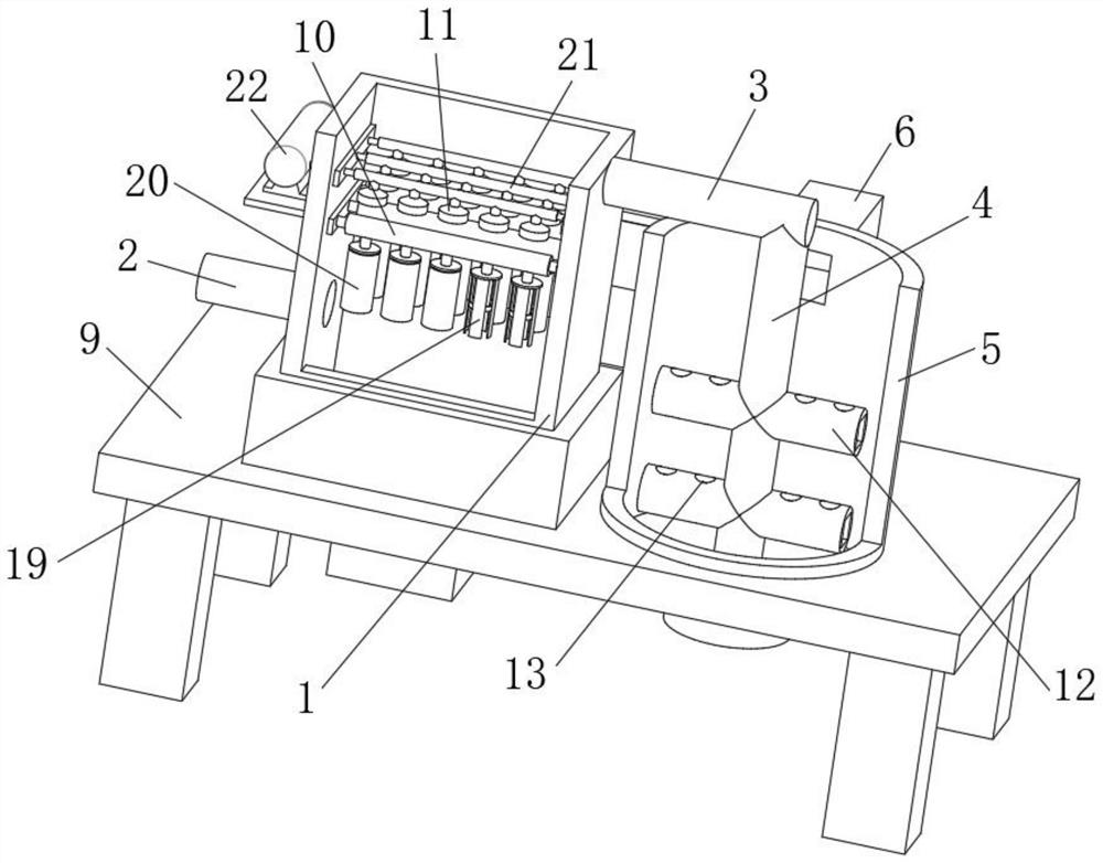
[0037] see figure 1 and image 3 , an exhaust gas treatment equipment for waste incineration, comprising an exhaust gas treatment equipment body 1, the exhaust gas treatment equipment body 1 is fixedly connected with an intake pipe 2, the installation of the intake pipe 2 provides a passage for exhaust gas to enter the interior of the exhaust gas treatment equipment body 1, and the exhaust gas The end of the processing equipment body 1 away from the intake pipe 2 is fixedly equipped with an outlet pipe 3, the outlet pipe 3 communicates with the air guide pipe 4, and a neutralization device 5 is installed outside the air guide pipe 4, and the installation of the neutralization device 5 plays a role in the protection of acid waste gas. The neutralization effect reduces the emission of acid waste gas. The neutralization device 5 is fixedly connected with an exhaust pipe 6, and the inner wall of the exhaust pipe 6 away from the neutralization device 5 is sleeved with a filter scre...
Embodiment 2
[0046] see Image 6 and Figure 7 , the lower end of the neutralization device 5 is connected with an auxiliary reaction device, and the auxiliary reaction device is fixedly arranged at the lower end of the base 9, and the auxiliary reaction device includes:
[0047] Auxiliary housing 23, the upper end of the auxiliary housing 23 is fixed to the lower end of the base 9, the upper front side of the auxiliary housing 23 is provided with a power chamber 2301, and the inside of the power chamber 2301 is fixed with a telescopic rod 1 30, the movable end of the telescopic rod 30 is fixedly connected with the lifting plate 31, the lifting plate 31 is evenly connected with a number of matching rods 32, and the matching rods 32 penetrate the upper end of the power chamber 1 2301 and the base 9 to enter the neutralization equipment The inside of 5 cooperates with through hole 13;
[0048] Liquid inlet 2303, the liquid inlet 2303 is arranged on the rear side of the upper end of the aux...
Embodiment 3
[0062] Also includes:
[0063] Speed sensor: the speed sensor is arranged at the entrance of the intake pipe 2, and is used to detect the flow rate of the exhaust gas at the entrance of the intake pipe 2;
[0064] Several weighing sensors: the several weighing sensors are respectively arranged at the connection between the venturi tube 10 and the exhaust gas treatment equipment body 1, and are used to detect the total mass of the venturi tube 10 and its connecting parts during the intake process of exhaust gas;
[0065] Alarm: the alarm is set on the surface of the waste treatment equipment body 1;
[0066] Controller: the controller is electrically connected to the speed sensor, load cell and alarm;
[0067] The controller controls the work of the alarm based on the speed sensor and the load cell, including the following steps:
[0068] Step 1: The controller calculates the theoretical dust load on the dust removal bag 20 when the exhaust gas is processed according to the...
PUM
 Abstract
Description
Claims
Application Information
 - R&D
- Intellectual Property
- Life Sciences
- Materials
- Tech Scout
- Unparalleled Data Quality
- Higher Quality Content
- 60% Fewer Hallucinations
Browse by: Latest US Patents, China's latest patents, Technical Efficacy Thesaurus, Application Domain, Technology Topic, Popular Technical Reports.
© 2025 PatSnap. All rights reserved.Legal|Privacy policy|Modern Slavery Act Transparency Statement|Sitemap|About US| Contact US: help@patsnap.com