Thick-wall pipeline weld joint multi-stage heating device and heating method

A heating device and pipeline technology, applied in induction heating devices, auxiliary devices, induction heating, etc., can solve the problems of increasing manufacturing costs, increasing power supply power, and unavoidable skin effect, so as to avoid cold welding and overheating , skin effect reduction, avoid the effect of skin effect

Active Publication Date: 2022-04-29
YANSHAN UNIV
View PDF7 Cites 1 Cited by
  • Summary
  • Abstract
  • Description
  • Claims
  • Application Information

AI Technical Summary

Problems solved by technology

The disadvantages of this traditional production process are: 1. There is a large wall thickness temperature difference at the weld of the tube blank
2. Not only is the efficiency low, but also because of the skin effect, the molten metal inside the tube blank drips and damages the magnetic rod
3. The equipment manufacturing cost is further increased by increasing the power supply
This method intends to reduce the temperature difference at the welding point by arranging multiple electrodes on the side of the tube blank in the thickness direction. However, because it applies a large pressure to the side surface of the tube blank due to the multiple electrodes arranged on the side of the tube blank, during the welding process, There is friction between the electrode and the side of the tube blank, which reduces the quality of the surface to be welded, and, Should In the method, the current flowing through the weld of the tube blank is still only a single circuit through the V-shaped corner apex of the weld, and the side walls of the tube blank on both sides of the weld are still heated unevenly, and the skin effect cannot be avoided in essence.
[0005] Some people also use induction heating to preheat the tube billet, but the speed of induction heating is far less than that of resistance heating, and it needs to add a power supply, which increases the manufacturing cost

Method used


Image

  • Thick-wall pipeline weld joint multi-stage heating device and heating method
  • Thick-wall pipeline weld joint multi-stage heating device and heating method
  • Thick-wall pipeline weld joint multi-stage heating device and heating method

Examples


Embodiment Construction

[0047] The structure and features of the present invention will be described in detail below in conjunction with the drawings and embodiments. It should be noted that various modifications can be made to the embodiments disclosed herein, therefore, the embodiments disclosed in the specification should not be regarded as limitations on the present invention, but only as examples of embodiments, and its purpose is to make the present invention The features of the invention are self-evident.

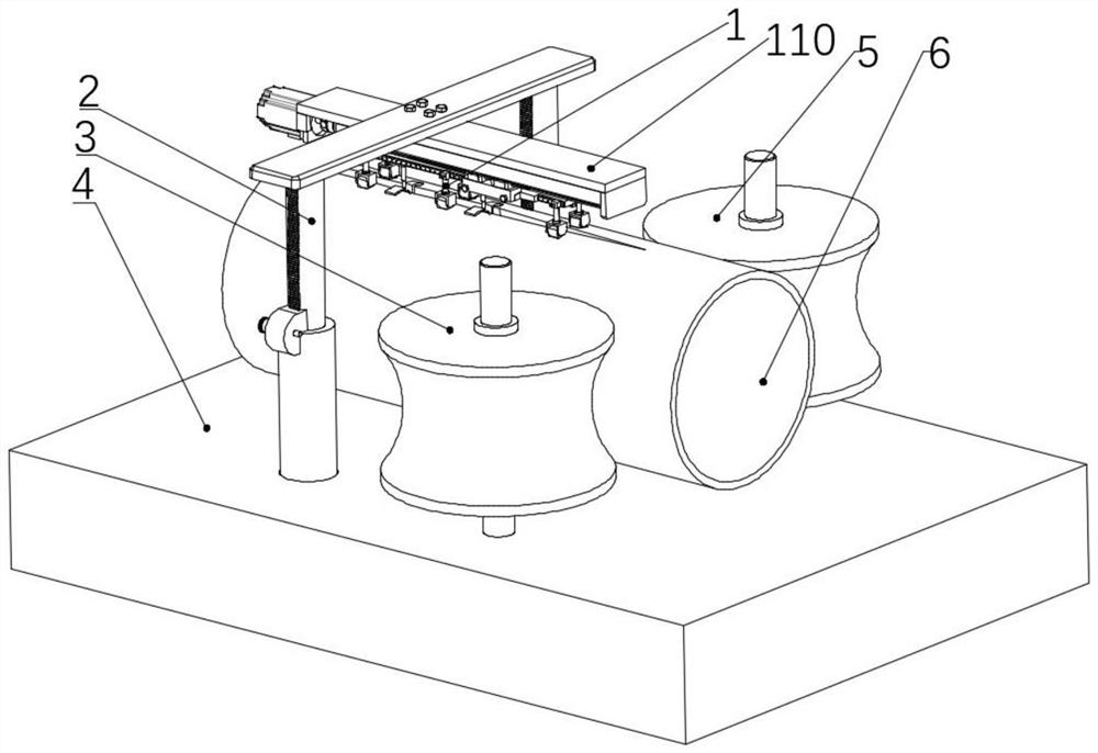
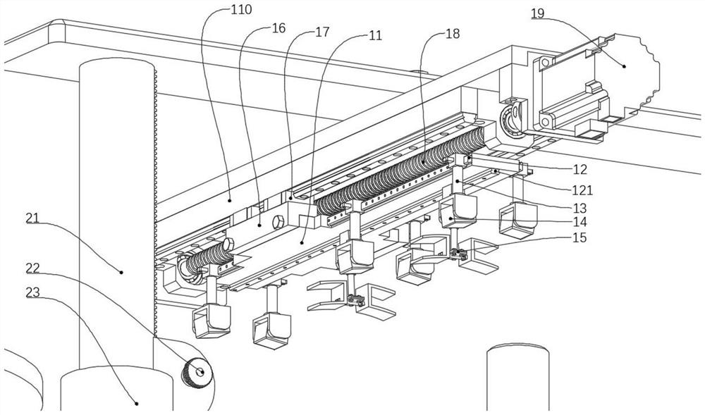
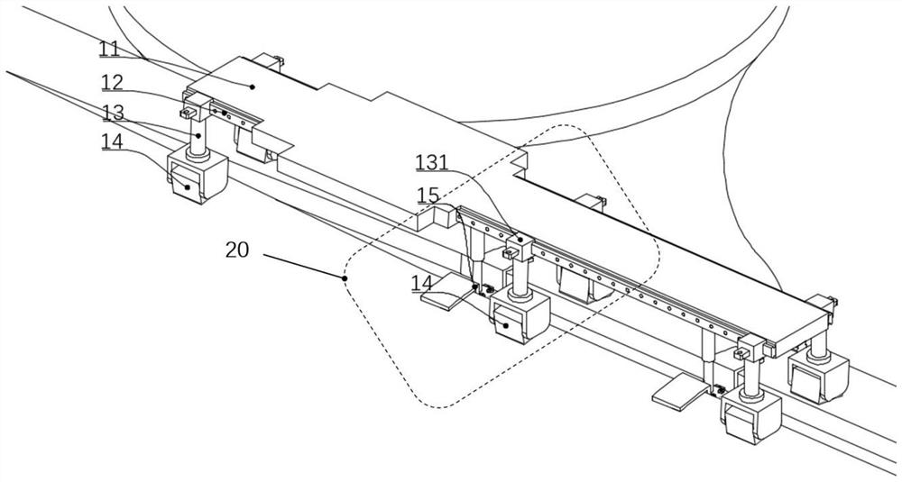
[0048] Such as figure 1 , figure 2 As shown, the thick-walled pipe weld multi-stage heating device of the present invention includes an electrode group 1 , a liftable gantry 2 , a left squeeze roller 3 , a welding platform 4 and a right squeeze roller 5 . The liftable gantry 2 is fixed on the welding platform 4, and the electrode group 1 is suspended below the middle of the liftable gantry 2, and the height of the electrode group 1 can be adjusted by adjusting the height of the liftable...


PUM


Abstract

The invention provides a thick-wall pipeline welding seam multi-stage heating device. The thick-wall pipeline welding seam multi-stage heating device comprises an electrode set, a liftable portal frame, a left extrusion roller, a welding platform and a right extrusion roller. And the electrode group is suspended and fixed below the liftable portal frame and is used for carrying out multi-stage heating on a welding seam. And the electrode group comprises a pair of common electrodes positioned near a V-shaped angle notch of the pipe blank and N movable electrode groups arranged at intervals. The invention further provides a method for uniformly heating the thick-wall pipe blank welding seam, the position of the movable electrode group is determined according to production requirements, then the movable electrode group is electrified and heated at the same time, a plurality of heating loops are formed at a plurality of positions on the side face of the pipe blank welding seam, and then a plurality of local heating currents are formed; the welding seam of the pipe blank reaches the peak of the V-shaped angle notch after being subjected to sufficient N times of heat conduction, and the temperature distribution at the welding seam of the pipe blank is more uniform. A multi-stage heating mode is formed through the common electrode and the N movable electrode sets, that is, multi-stage heating is conducted on the weld joint of the pipe blank through the multiple movable electrodes arranged at intervals, and the weld joint of the pipe blank is evenly heated.

Description

technical field [0001] The invention relates to a thick-walled pipe weld seam heating device and a heating method, in particular, the invention relates to a thick-wall pipe weld seam heated by multi-stage heating so that the thick-wall pipe weld seam is evenly heated The utility model relates to a multi-stage heating device and a heating method for pipeline weld seams. The invention belongs to the technical field of high-frequency resistance welding pipes. Background technique [0002] After the 20th century, with the tight oil supply situation in the world, some oil and gas fields with very harsh geological and environmental conditions have been put into development one after another, and the requirements for pipelines for transporting crude oil are more stringent, thus bringing the pipeline industry into a new period. In particular, pipelines and submarine pipelines for transporting crude oil over long distances are becoming thicker. [0003] Due to the high cost of thic...

Claims


Application Information

Patent Timeline
Patent Type & Authority Applications(China)
IPC IPC(8): B23K37/00H05B6/10
CPCB23K37/00H05B6/10
Inventor 韩毅牛轩煜肖瑶
Owner YANSHAN UNIV
Why Eureka
Try Eureka