
Glass block forming device and forming method thereof

A molding device and molding method technology, applied in glass molding, glass manufacturing equipment, manufacturing tools, etc., can solve the problems of limited temperature field uniformity, local stress concentration of products, and affecting product quality, etc., to achieve temperature field uniformity The effect of reducing and reducing the heat dissipation speed and improving the qualified rate of molded products

Pending Publication Date: 2022-04-29
CDGM GLASS LLC
View PDF2 Cites 0 Cited by
  • Summary
  • Abstract
  • Description
  • Claims
  • Application Information

AI Technical Summary

Problems solved by technology

It can be seen from the literature that the flow uniformity and temperature field uniformity of glass in the leakage casting molding process directly affect the internal quality and external shape of the formed product, and the effect of improving the temperature field uniformity by preheating, bottom fire head, and ceramic insulators is relatively low. Limited, and preheating the mold will easily lead to problems such as excessive temperature of the mold during the molding process of the glass, resulting in bubbles at the molding interface, mold breakage, etc., and adding a substrate material with low thermal conductivity on the surface in contact with the glass liquid will easily lead to its contact with the glass liquid. Due to the many and large gaps in the interface, bubbles are formed at the interface and glass liquid crystallization is induced, resulting in local stress concentration of subsequent products, thereby affecting product quality, and even causing glass to burst in the subsequent annealing process

Method used


Image

  • Glass block forming device and forming method thereof
  • Glass block forming device and forming method thereof
  • Glass block forming device and forming method thereof

Examples


Embodiment Construction

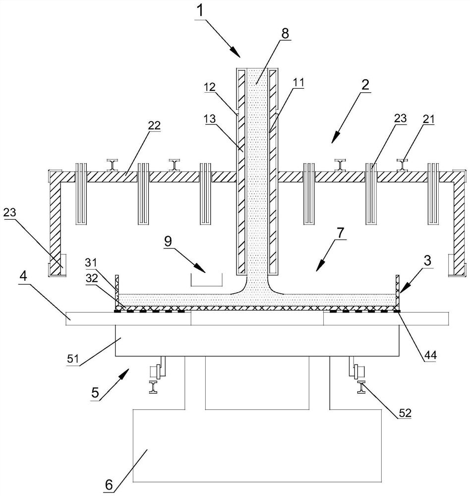
[0034] The glass block forming device of the present invention includes a discharge pipe 1, a soaking cover 2, a forming mold 3, a heat dissipation support 4, a transfer device 5 and a lifting device 6, such as figure 1shown. The discharge pipe 1 passes through the top of the soaking cover through the round hole of the soaking cover and enters the molding space 7 formed by the soaking cover 2 and the forming mold 3. A certain distance; the forming mold 3 is located directly under the soaking cover 2, and the glass liquid flows out from the discharge pipe 1 to complete shaping in the forming space 7; the heat dissipation bracket 4 is placed under the bottom of the forming mold 3 for balanced forming The heat in each area of ​​the lower surface of the bottom mold of the mold 3 is dissipated, and bears the pressure of the forming mold 3 and the formed glass liquid to prevent the glass surface from being subjected to tensile stress and cracks due to the deformation of the forming ...


PUM


Abstract

The invention provides a glass block forming device capable of improving the fluidity of molten glass in the forming process and the uniformity of a temperature field. According to the glass block forming device, a discharging pipe penetrates through the top of a soaking cover to enter a forming space formed by the soaking cover and a forming mold; the forming mold is located under the soaking cover; the heat dissipation support is placed below the forming die. The transfer device is located on the lower portion of the heat dissipation support and supports and transfers the heat dissipation support and the forming die. The lifting device is located below the transfer device and supports and controls the vertical movement speed of the forming mold, the heat dissipation support and the transfer device. The heat dissipation rate of the center area of the bottom die is increased, the heat dissipation speed of the edge area of the bottom die is reduced, the temperature field uniformity of the bottom die is improved, and the temperature uniformity of radial flow in molten glass forming flow is improved; bubbles formed by micropores on a contact interface and the growth overflow speed of the bubbles when the inner surface of the bottom die is in contact with molten glass can be controlled, and the defect that interface bubbles enter the molten glass to form formed bubbles is avoided.

Description

technical field [0001] The invention relates to a forming device for glass blocks and a forming method for improving the uniformity of glass liquid in the forming process through the forming device. Background technique [0002] Due to the advantages of large monomer size, good optical properties, strong chemical stability, and controlled expansion, large-caliber glass blocks are used in astronomical observation fields such as large telescopes and mirrors. The production process of this type of glass is similar to the production of ordinary optical glass. It still needs to go through main thermal processes such as powder melting, clarification, homogenization, molding, and cooling to obtain bulk glass products. However, in the above process, the process The conditions are more harsh than ordinary glass, and the forming process of large-diameter glass blocks is very important. This process determines the shape and size of the final product, and also affects the inner quality ...

Claims


Application Information

Patent Timeline
IPC IPC(8): C03B19/02
CPCC03B19/02Y02P40/57
Inventor 郭富强陈筱丽周思宇刘小宁王乃帅
Owner CDGM GLASS LLC
Learn More