
Large-angle transmitting-receiving synchronous laser radar optical system

An optical system and a technology of transmitting and receiving synchronization, applied in the field of laser radar optical system, can solve the problems that MEMS scanning galvanometer is not compatible with large scanning angle, MEMS laser radar is not compatible, etc.

Pending Publication Date: 2022-04-29
XI AN ZHISENSOR TECH CO LTD
View PDF0 Cites 0 Cited by
  • Summary
  • Abstract
  • Description
  • Claims
  • Application Information

AI Technical Summary

Problems solved by technology

[0006] Aiming at the problem that the MEMS laser radar cannot be compatible with large detection field of view, high detection frame rate and long-distance detection because the MEMS scanning galvanometer cannot be compatible with large scanning angle, high resonance frequency and large receiving area, the present invention proposes a large-angle transceiver Synchronized lidar optics
Both one-dimensional and two-dimensional MEMS scanning mirrors are available

Method used


Image

  • Large-angle transmitting-receiving synchronous laser radar optical system
  • Large-angle transmitting-receiving synchronous laser radar optical system
  • Large-angle transmitting-receiving synchronous laser radar optical system

Examples


Embodiment 1

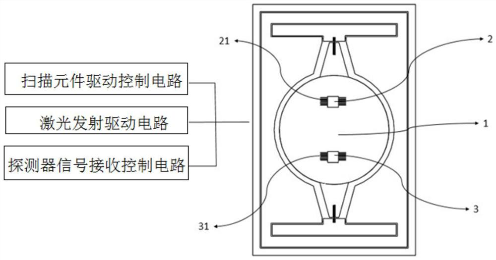
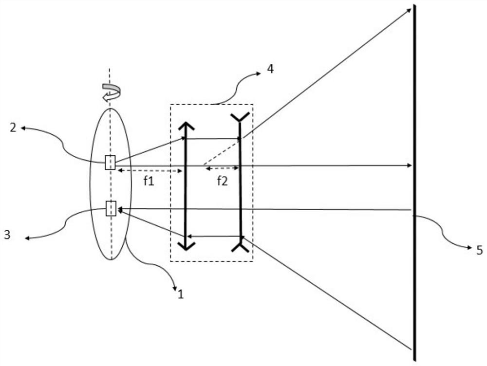
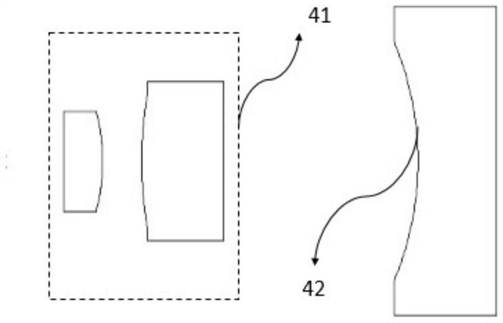
[0043] This embodiment proposes a large-angle transceiver synchronous MEMS lidar optical system, including a MEMS scanning galvanometer module, a circuit integrated control module, and an angle-expanding optical system module; the MEMS scanning galvanometer module includes a one-dimensional or two-dimensional MEMS scanning galvanometer 1. The laser emitting chip and the photodetector responding chip, the laser emitting chip and the photodetector responding chip are implanted on the surface of the MEMS scanning vibrating mirror, and follow the MEMS scanning vibrating mirror to scan synchronously. In this embodiment, on the basis of the conventional MEMS scanning galvanometer processing method, the laser emission chip and the photodetector response chip are implanted on the surface of the MEMS scanning galvanometer, and the laser emission drive circuit and the detector signal receiving control circuit are realized through leads. The conduction of the circuit is performed outside ...

Embodiment 2

[0057] Figure 4 As another embodiment of the present invention, the method of expanding the radar scanning field of view can be realized by combining and splicing scanning modules. In this embodiment, n MEMS scanning galvanometer modules are selected for realization. The large-angle transmitting and receiving synchronous MEMS laser radar optical system of this embodiment includes n MEMS scanning galvanometer modules and n circuit integrated control modules corresponding thereto; wherein n is a positive integer greater than or equal to 2; Figure 4 Among them, 11 is the first MEMS scanning galvanometer module, 12 is the second MEMS scanning galvanometer module, and 1n is the nth MEMS scanning galvanometer module.

[0058] Each MEMS scanning galvanometer module is the same as Embodiment 1, and includes a MEMS scanning galvanometer and a laser emission chip and a photodetector response chip implanted on the surface of the MEMS scanning galvanometer; the laser emission chip and t...


PUM

PropertyMeasurementUnit
wavelengthaaaaaaaaaa
sizeaaaaaaaaaa

Abstract

The invention belongs to the field of laser radar optical systems, and relates to a large-angle transceiving synchronous laser radar optical system. The problem that an existing MEMS laser radar cannot be compatible with large detection view field, high detection frame rate and long-distance detection is solved. A laser emission chip and a photoelectric detector response chip are implanted into the surface of an MEMS scanning galvanometer type scanning element. While the MEMS scanning galvanometer is controlled to vibrate, the laser emission chip is controlled to emit laser and the photoelectric detector response chip is controlled to receive the response of a signal, and the laser emission light source does not need to be reflected by the surface of the MEMS scanning galvanometer, namely, the MEMS scanning galvanometer does not play a role of a scanning reflector any more. The laser emission chip can directly follow the MEMS scanning galvanometer to scan and emit light, and meanwhile, an angle-expanding optical system is arranged outside or field splicing is carried out to shape small-angle scanning into wide-angle scanning emission, so that the restriction of the area size of the MEMS scanning galvanometer on the scanning resonant frequency and the scanning angle is weakened.

Description

technical field [0001] The invention belongs to the field of laser radar optical systems, and relates to a large-angle transmitting and receiving synchronous laser radar optical system. Background technique [0002] There are several ways to use laser radar to achieve ranging and three-dimensional imaging: 1. Traditional mechanical rotary scanning, which drives the laser radar to rotate 360° through a mechanical device; this type of system has the problem of large dimensions and serious wear and tear after a long time ; 2, all-solid-state scanning (such as optical phased array), change the emission angle by adjusting the phase difference of each emission unit in the emission array; this type of system has the problem that the cost of core components is too high; 3, MEMS (micro-electromechanical system ) hybrid solid-state scanning can be made into a one-dimensional or two-dimensional MEMS scanning galvanometer scanning surface, and only one laser beam can scan the entire det...

Claims


Application Information

Patent Timeline
Patent Type & Authority Applications(China)
IPC IPC(8): G01S7/481G01S17/10G01S17/894
CPCG01S7/4817G01S17/10G01S17/894
Inventor 范乔丹夏长锋郑文会张艳妮
Owner XI AN ZHISENSOR TECH CO LTD
Learn More