First wall structure for fusion reactor high-dose neutron irradiation and megawatt-level thermal load

A high-dose, fusion reactor technology, applied in the field of fusion reactors, can solve the problems of the helium-cooled first wall being unable to meet the needs of CFETR fusion reactors, limiting the heat-carrying capacity and service life of the first wall, and failing to meet the high heat load of fusion reactors, etc. Achieve the effect of improving thermoelectric conversion efficiency, improving the comprehensiveness of anti-irradiation and high thermal load resistance, and improving high thermal load bearing capacity

Pending Publication Date: 2022-04-29
SOUTHWESTERN INST OF PHYSICS
View PDF10 Cites 0 Cited by
  • Summary
  • Abstract
  • Description
  • Claims
  • Application Information

AI Technical Summary

Problems solved by technology

[0004] The existing helium-cooled first wall cannot meet the needs of CFETR and future fusion reactors
Its main disadvantages are: (1) Low-activation ferrite / martensitic stainless steel (RAFMs) is mainly used as the structural material. The upper limit of the allowable temperature of RAFMs steel is 550°C, and the allowable limit of neutron irradiation is 20dpa, which seriously limits the The heat carrying capacity and service life of the first wall; (2) The heat carrying capacity of the first wall is about 0.3-0.5MW / m 2 , unable to meet up to 1MW / m 2 (3) The inlet / outlet temperature of the first wall coolant is about 300 / 500°C, and the operating temperature of the working fluid is relatively low, so the thermoelectric conversion efficiency is low, which is not conducive to the economical operation of the fusion reactor

Method used


Image

  • First wall structure for fusion reactor high-dose neutron irradiation and megawatt-level thermal load
  • First wall structure for fusion reactor high-dose neutron irradiation and megawatt-level thermal load
  • First wall structure for fusion reactor high-dose neutron irradiation and megawatt-level thermal load

Examples


Embodiment Construction

[0028] The present invention will be described in further detail below in conjunction with the accompanying drawings and embodiments.

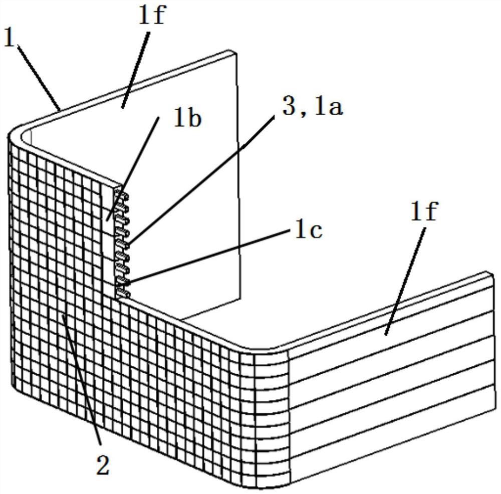
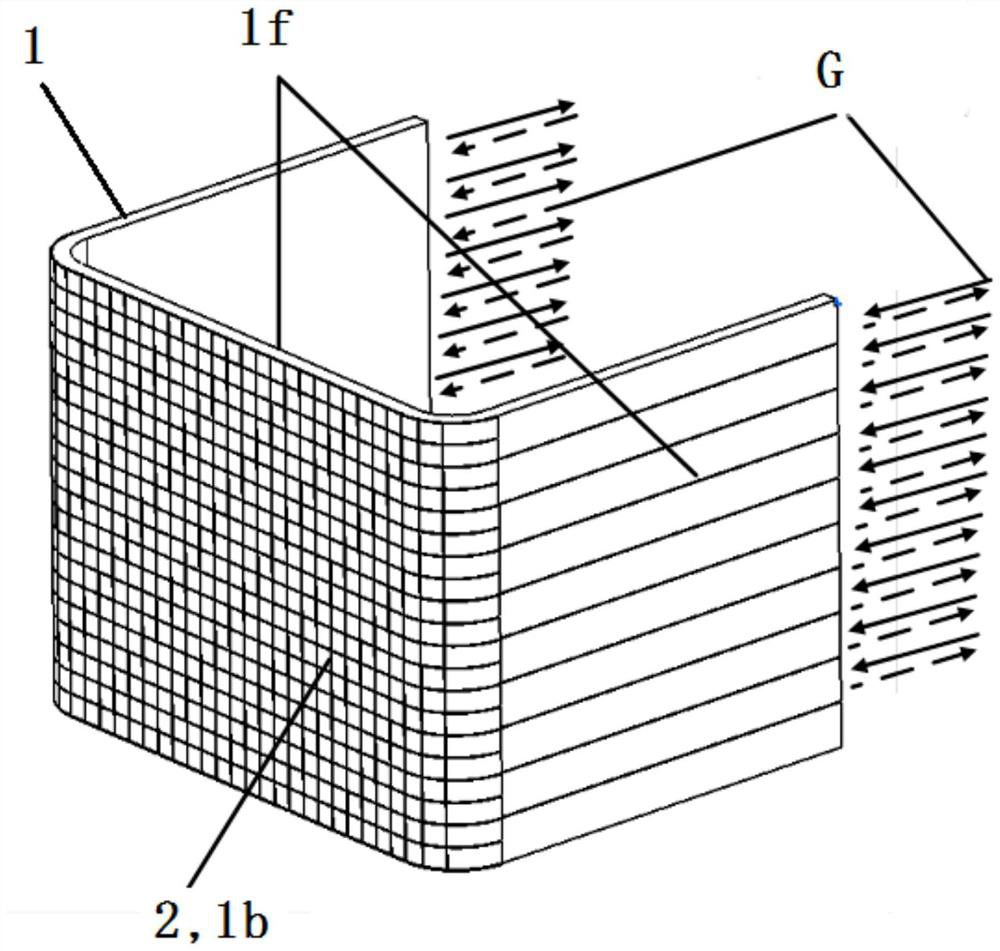
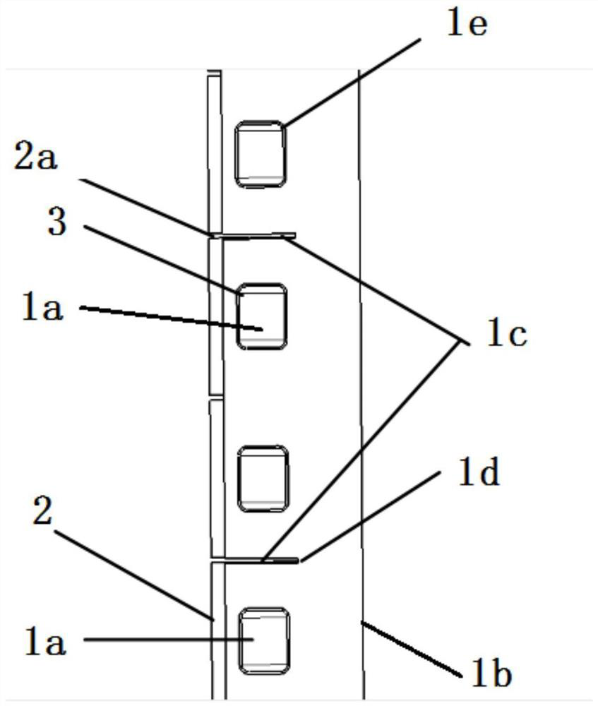
[0029] Such as figure 1 , figure 2 with image 3 As shown, the present invention provides a first wall structure for fusion reactor neutron irradiation and megawatt heat load, the first wall structure includes a first wall body 1, a protective layer 2 and a flow channel lining 3. The first wall body 1 is in the shape of a "U" as a whole. There are 10 flow channels 1a arranged parallel to each other in the first wall body 1. The front wall 1b of the first wall body 1 has 9 flow channels 1a arranged in parallel in the lateral direction. Gap 1c between runners, each gap 1c between runners is located between the upper and lower runners; each gap 1c between runners is provided with gap chamfering 1d between runners, each runner 1a is equipped with a runner Chamfer 1e. Each flow channel 1a is welded with a flow channel liner 3 . The outer sur...


PUM


Abstract

The invention belongs to the technical field of fusion reactors, and particularly relates to a first wall structure for high-dose neutron irradiation and megawatt-level thermal load of a fusion reactor, and the first wall structure comprises a first wall body, a protection layer and a flow channel lining; a protective layer is arranged on the outer side of the front wall of the first wall body, flow channels used for coolant circulation are formed in the first wall body, the flow channel linings are located in the flow channels, a plurality of flow channels which are arranged in parallel in the transverse direction are formed in the first wall body, and flow channel gaps are formed between the flow channels in the first wall body. The first wall body is made of V-(4-5)% Cr-(4-5)% Ti vanadium alloy, the protective layer is in a tungsten tile shape, and the runner lining is made of a low-activation ferrite / martensitic stainless steel RAFMs thin wall. The first wall is long in service life, can bear 1MW / m < 2 > surface high heat load, is high in coolant operation temperature, and can meet the requirements of a CFETR and a future fusion reactor first wall.

Description

technical field [0001] The invention belongs to the technical field of fusion reactors, and in particular relates to a first wall structure for high-dose neutron irradiation and megawatt-level heat load of fusion reactors. Background technique [0002] Nuclear fusion energy is the main energy source for future human beings. In the fusion reaction, the Lawson criterion is reached by heating and confining the deuterium-tritium fuel to form a high-temperature plasma of hundreds of millions of degrees. When the deuterium-tritium nuclear fusion reaction will release up to 17.4MeV fusion energy, which contains 14MeV high-energy fusion neutrons. [0003] The first wall is a high heat load component directly facing the plasma, which covers more than 80% of the high temperature plasma. The 14MeV high-energy neutrons produced by the fusion reaction will act on the first wall, resulting in severe radiation damage. With the increase of operating time, the radiation damage of the struc...

Claims


Application Information

Patent Timeline
Patent Type & Authority Applications(China)
IPC IPC(8): G21B1/13
CPCG21B1/13Y02E30/10
Inventor 谌继明王小勇栗再新郑鹏飞李佳霖廖洪彬张归航
Owner SOUTHWESTERN INST OF PHYSICS
Why Eureka
Try Eureka