Biomass particle conduction oil boiler
A heat-conducting oil boiler and biomass particle technology, applied in heat storage heaters, fluid heaters, clean heat transfer devices, etc., can solve the problems of heat waste, low heat exchange efficiency, and short heat exchange time of heat conduction oil, and achieve Enhance heat transfer time, improve heat transfer efficiency, and slow down the effect of moving speed
- Summary
- Abstract
- Description
- Claims
- Application Information
AI Technical Summary
Problems solved by technology
Method used
Image
Examples
Embodiment 1
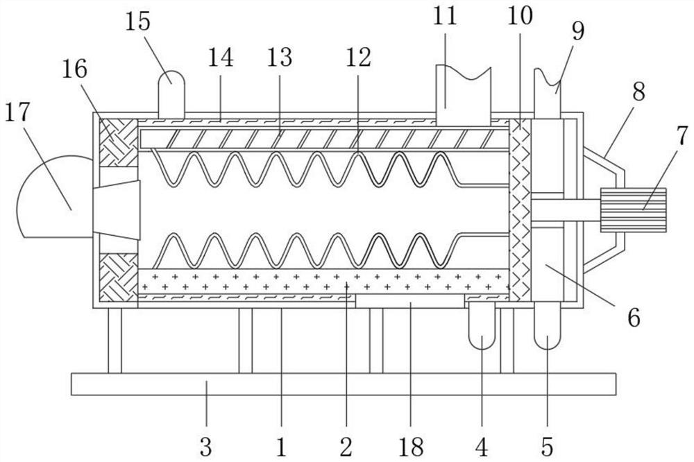
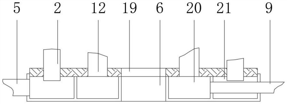
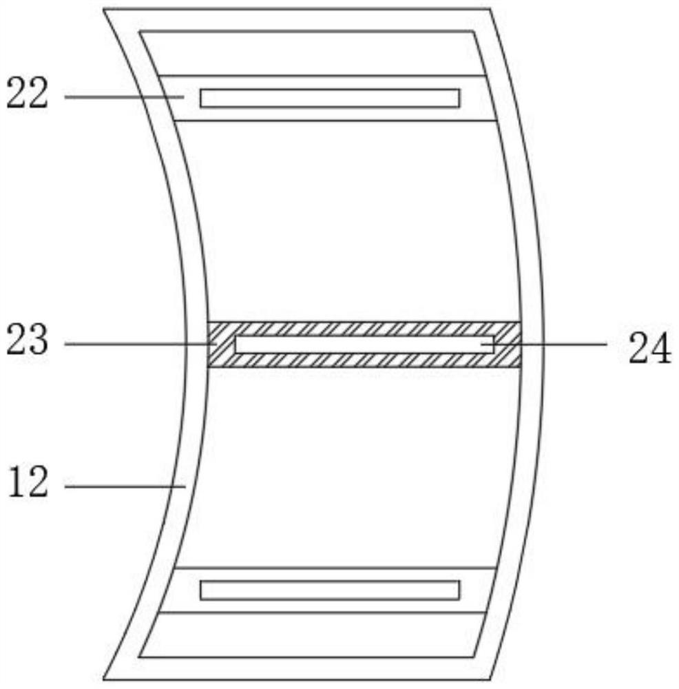
[0038] refer to Figure 1-5 , a biomass particle heat-conducting oil boiler, including a support base 3, a furnace body 1 is fixedly installed on the top of the support base 3, and a burner 17 is fixedly installed on the upper end of the outer wall of one side of the furnace body 1, and the outer wall of the other side of the furnace body 1 is fixed A fixed frame 8 is installed, and a drive motor 7 is fixedly installed in the middle of the fixed frame 8, and the output end of the drive motor 7 is sequentially provided with an intermediate oil tank 6 and a fixed plate 10, and the intermediate oil tank 6 and the fixed plate 10 are located on the other side of the furnace body 1. , a plurality of equiangular heat exchange shells 2 are fixedly installed on the outside of the fixed plate 10, and a positioning bearing 16 is fixedly installed on one side of the furnace body 1, the end of the heat exchange shell 2 is inside the positioning bearing 16, and the inner sides of the heat ex...
Embodiment 2
[0049] refer to Figure 6-7 , a biomass particle heat-conducting oil boiler, further, a wave plate 29 is fixedly installed in the middle of the inner side of the heat exchange shell 2, and the wave plate 29 is provided with several equidistant conical openings 30, and the wave plate 29 is fixedly installed with several Equidistant spoiler rods 31, each spoiler rod 31 is located in the middle of the tapered opening 30, and each spoiler rod 31 is rotated 20° outward;
[0050] Wherein, the wave plate 29 and the spoiler rod 31 are both in the shape of a 2sinx function graph, and the coil pipe 12 is in the shape of a 5sin(0.5x) function graph.
[0051] Working principle: The wave plate 29 is fixedly installed in the middle of the inner side of the heat exchange shell 2. The wave plate 29 is provided with several equidistant conical openings 30. The flow rod 31 has the left and right sides of blocking and disturbing the biomass slag and the thermal energy airflow, prolonging the st...
Embodiment 3
[0053] refer to Figure 1-5 And 8, a biomass particle heat-conducting oil boiler, including a support base 3, a furnace body 1 is fixedly installed on the top of the support base 3, and a burner 17 is fixedly installed on the upper end of the outer wall of one side of the furnace body 1, and the other side of the furnace body 1 The outer wall is fixedly equipped with a fixed frame 8, and the middle of the fixed frame 8 is fixedly equipped with a drive motor 7, and the output end of the drive motor 7 is sequentially provided with an intermediate oil tank 6 and a fixed plate 10, and the intermediate oil tank 6 and the fixed plate 10 are located on the other side of the furnace body 1. On one side, a plurality of equiangular heat exchange shells 2 are fixedly installed on the outside of the fixed plate 10, and a positioning bearing 16 is fixedly installed on the inner side of the furnace body 1, and the end of the heat exchange shell 2 is inside the positioning bearing 16, and the...
PUM
 Abstract
Description
Claims
Application Information
 - R&D
- Intellectual Property
- Life Sciences
- Materials
- Tech Scout
- Unparalleled Data Quality
- Higher Quality Content
- 60% Fewer Hallucinations
Browse by: Latest US Patents, China's latest patents, Technical Efficacy Thesaurus, Application Domain, Technology Topic, Popular Technical Reports.
© 2025 PatSnap. All rights reserved.Legal|Privacy policy|Modern Slavery Act Transparency Statement|Sitemap|About US| Contact US: help@patsnap.com


