
Combustor capable of achieving sufficient combustion and using method thereof

A full combustion, burner technology, applied in the combustion method, solid fuel combustion, combustion equipment and other directions, can solve the problems of affecting the combustion effect, easy dust clogging, poor fuel usage rate, etc., to improve the convenience of feeding and ensure combustion. Efficiency, improved uniformity effect

Active Publication Date: 2022-05-10
江苏旭润机电科技有限公司
View PDF4 Cites 0 Cited by
  • Summary
  • Abstract
  • Description
  • Claims
  • Application Information

AI Technical Summary

Problems solved by technology

[0003]1. The pellet fuel in the existing burner pair cannot be fully burned, resulting in poor fuel utilization and waste;
[0004]2. Secondly, the existing burner cannot collect the internal dust, which makes the dust easy to block and affects the combustion effect

Method used


Image

  • Combustor capable of achieving sufficient combustion and using method thereof
  • Combustor capable of achieving sufficient combustion and using method thereof
  • Combustor capable of achieving sufficient combustion and using method thereof

Examples


Embodiment 1

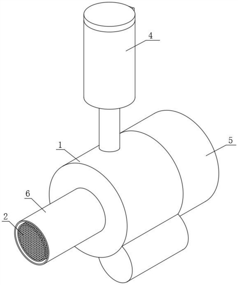
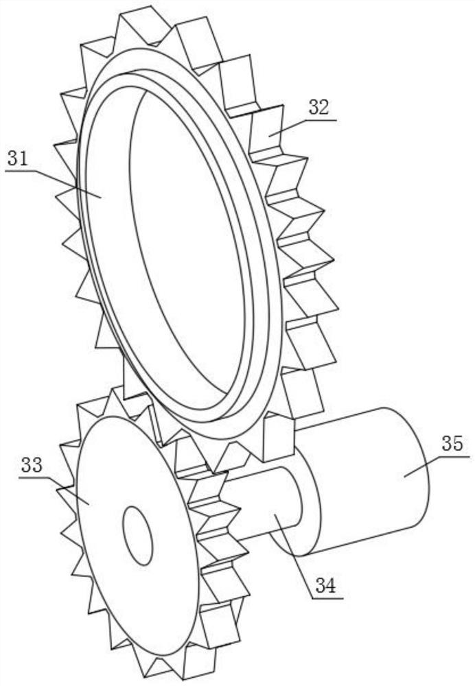
[0038] see figure 1, a fully combustible burner and its use method, comprising a casing 1, a combustion device 2 is arranged inside the casing 1, a transmission assembly 3 is sleeved on one end of the combustion device 2, and a feeding material is connected to the rear of the combustion device 2 Device 4, the rear of the feeding device 4 is provided with an air blowing device 5, one end of the air blowing device 5 is connected to one end of the combustion device 2, and the front end of the combustion device 2 is provided with a dust removal device 6.

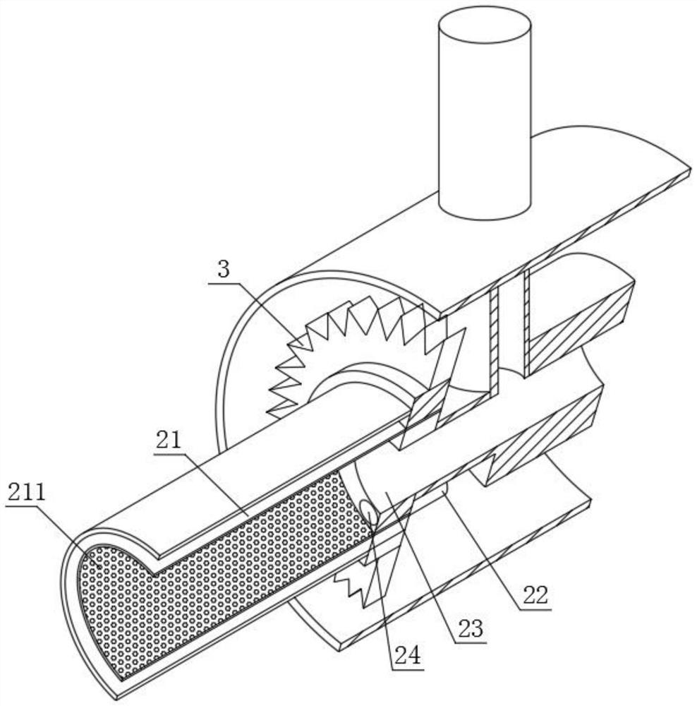
[0039] see figure 2 , the combustion device 2 comprises a combustion pipeline 21, a burner 22, a material port 23 and a combustion port 24, the bottom center of the combustion channel 21 is provided with a material port 23, and the bottom of the combustion channel 21 below the material port 23 is provided with a combustion port 24 , a burner 22 is provided in the combustion port 24, an ash discharge port 211 is provided on the...

Embodiment 2

[0050] see Figure 7-Figure 8 , the top of the cleaning device 6 is also provided with a gas processing device 7, the gas processing device 7 includes a gas outlet pipe 71, a processing tank body 72, a built-in tank body 73 and a processing assembly 74, and the gas outlet pipe 71 communicates with the dust cleaning device 6, and the gas outlet pipe 71 communicates with the cleaning device 6. The top of the air pipe 71 communicates with the built-in tank body 73, the processing tank body 72 is sleeved on the outside of the built-in tank body 73, a heat exchange tank 731 is opened between the processing tank body 72 and the built-in tank body 73, and the inside of the built-in tank body 73 A processing assembly 74 is provided. The processing assembly 74 includes an impurity filter plate 741, an adsorption layer 742 and an exhaust pipe 743. The impurity filter plate 741 is arranged inside the built-in tank body 73, and two layers of adsorption layers 742 are arranged above the imp...


PUM


Abstract

The invention discloses a combustor capable of achieving sufficient combustion and a using method of the combustor, belongs to the technical field of combustors, and aims to solve the problems that the fuel utilization rate is low, waste is caused, internal dust cannot be collected by an existing combustor, dust is prone to blockage, and the combustion effect is affected. The sleeving ring drives the combustion pipeline to rotate, so that granular fuel in the combustion pipeline is rotated, the combustion uniformity of the whole granular fuel is improved, the combustion efficiency is guaranteed, the sleeving ring is matched with the ash discharge port while the combustion pipeline is driven to rotate, and dust generated after rotation combustion is discharged into the ash removal device through the ash discharge port; the waste ash is effectively collected, air is blown through the ventilation opening and the combustion pipeline, granular fuel can be combusted more evenly, under the action of the air, the granular fuel can be fully combusted, fuel waste caused by insufficient combustion is prevented, and the utilization rate of the fuel is increased.

Description

technical field [0001] The invention relates to the technical field of burners, in particular to a fully combustible burner and a usage method thereof. Background technique [0002] The burner is a general term for devices that make fuel and air spray out and combust in a certain way. Burners are divided into industrial burners, burners, civil burners, and special burners according to types and application fields. It is mostly made of corrosion-resistant and high-temperature-resistant materials such as stainless steel or metal titanium. The function of the burner is to atomize the sample by flame combustion. The atomized test solution enters the burner, and under the action of flame temperature and flame atmosphere, it undergoes drying, melting, evaporation, dissociation and other processes to produce a large number of ground state atoms, as well as some excited state atoms, ions and molecules. [0003] 1. The pellet fuel in the existing burner pair cannot be fully burned...

Claims


Application Information

Patent Timeline
Patent Type & Authority Applications(China)
IPC IPC(8): F23B30/02F23K3/14F23L5/02F23J1/00F23J3/00
CPCF23B30/02F23K3/14F23L5/02F23J1/00F23J3/00
Inventor 徐国胤
Owner 江苏旭润机电科技有限公司
Learn More