

Charge transport material and organic electroluminescent device
A charge transport, non-replacement technology, applied in the field of organic electroluminescent devices, can solve the problems of shortened life, increased driving voltage, reduced luminous efficiency, etc., and achieve the effect of high charge transfer ability and high stability
- Summary
- Abstract
- Description
- Claims
- Application Information
AI Technical Summary
Problems solved by technology
Method used
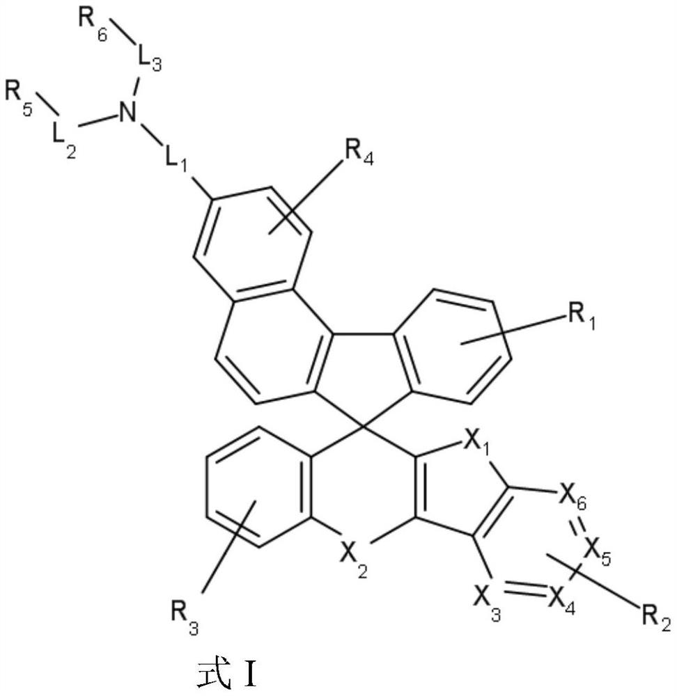
Image

Examples
Embodiment 1
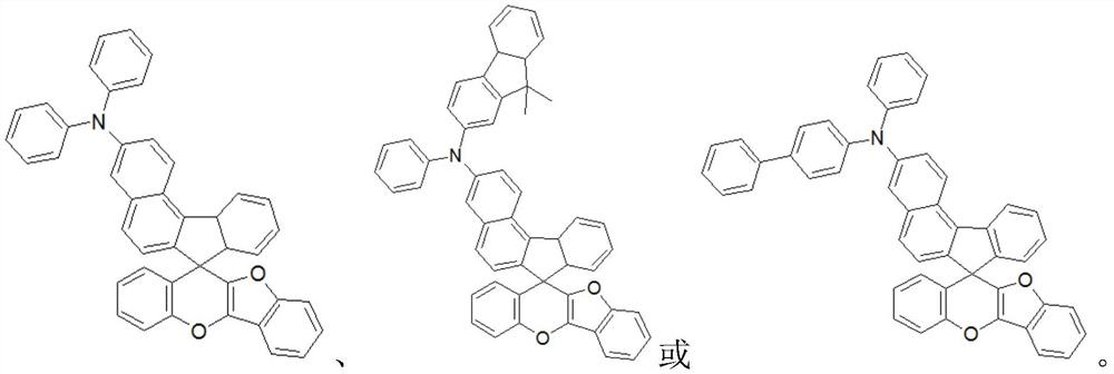
[0035] The synthetic method for preparing compound 1 is as follows:
[0036]
[0037] Compound Z
[0038] Add 4g of compound Z, 2g of anhydrous cesium carbonate powder, and 0.3g of Pd in a 200mL three-neck flask 2 dba 3 , then add 100mL of anhydrous 1,4-dioxane and stir well. During the process, nitrogen was supplemented while vacuuming, so that the reaction was in a nitrogen atmosphere. Keep heating at 100°C, add 1.5 g of the compound diphenylamine dropwise, reflux for 24 hours in the dark, and track the plate until the reaction is complete. After recrystallization at lower temperature, 3.1 g of compound 1 was obtained through column chromatography (60% yield).
[0039] Analytical data: Tm 310°C, purity 99.9%, 1H NMR (400MHz, DMSO) δ8.06(m, 1H), 7.61(m, 1H), 7.5(m, 1H), 7.48(m, 1H), 7.44( m,1H),7.4(m,1H),7.34(m,1H),7.24(m,1H),7.2(m,1H),7.15(m,1H),7.1(m,1H),7.01(m ,4H),6.90(m,1H),6.89(m,1H),6.80(m,1H),6.75(m,1H),6.70(m,1H),6.75(m,1H),6.62(m, 2H), 6.46 (m, 4H).
Embodiment 2
[0041] The synthetic method for preparing compound 2 is as follows:
[0042]
[0043] Compound Z
[0044] The synthesis method of compound 2 was similar to that of compound 1, and 3.6 g of compound 2 was obtained (yield 54%).
[0045] Analytical data: Tm 340°C, purity 99.9%, 1H NMR (400MHz, DMSO) δ8.06(m, 1H), 7.84(m, 1H), 7.61(m, 1H), 7.59(m, 1H), 7.55( m,1H),7.5(m,1H),7.48(m,1H),7.44(m,1H),7.4(m,1H),7.38(m,1H),7.34(m,1H),7.28(m ,1H),7.24(m,1H),7.2(m,1H),7.15(m,1H),7.1(m,1H),7.01(m,2H),6.90(m,1H),6.89(m, 1H),6.80(m,1H),6.75(m,2H),6.70(m,1H),6.62(m,1H),6.61(m,1H),6.58(m,1H),6.46(m,2H ), 1.67(s,6H).
Embodiment 3
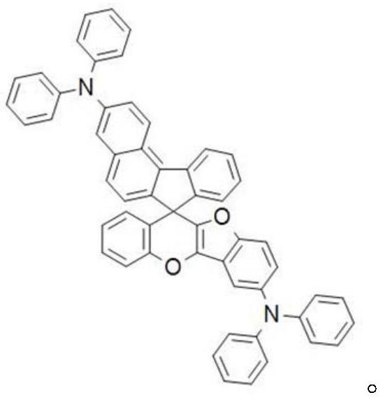
[0047] The synthetic method for preparing compound 3 is as follows:
[0048]
[0049] Compound Z
[0050] The synthesis method of compound 3 was similar to that of compound 1, and 4.2 g of compound 3 was obtained (yield 53%).
[0051]Analytical data: Tm 313°C, purity 99.9%, 1H NMR (400MHz, DMSO) δ8.24(m, 1H), 7.84(m, 1H), 7.75(m, 2H), 7.74(m, 1H), 7.73( m,1H),7.64(m,1H),7.59(m,1H),7.57(m,1H),7.55(m,2H),7.49(m,2H),7.43(m,1H),7.41(m ,1H),7.39(m,1H),7.38(m,1H),7.37(m,2H),7.31(m,1H),7.24(m,2H),7.18(m,1H),7.08(m, 2H), 7.01(m,1H), 7.00(m,1H), 6.98(m,1H), 6.85(m,1H), 6.82(m,1H), 6.77(m,1H).
PUM
| Property | Measurement | Unit |
|---|---|---|
| thickness | aaaaa | aaaaa |
| thickness | aaaaa | aaaaa |
| thickness | aaaaa | aaaaa |
Abstract
Description
Claims
Application Information