Sterility testing device for medical apparatus and instruments
A technology for sterility inspection and medical equipment, applied in the medical field, can solve the problems of bacteria not being cleaned, cross-infection, reducing the work efficiency of staff, etc., so as to reduce the probability of infection and enhance the effect of elution.
- Summary
- Abstract
- Description
- Claims
- Application Information
AI Technical Summary
Problems solved by technology
Method used
Image

Examples
Embodiment 1
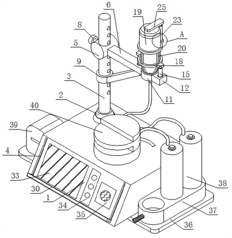
[0049] like figure 1 and figure 2 As shown, a sterility inspection device for medical equipment includes an inspection body 1, a fixed seat 2, a column 3 and a chute 4. The top of the inspection body 1 is installed with a fixed seat 2, and the top of the fixed seat 2 is installed with a column 3;
[0050] Two sets of chutes 4 arranged side by side are installed on the front of the inspection body 1;
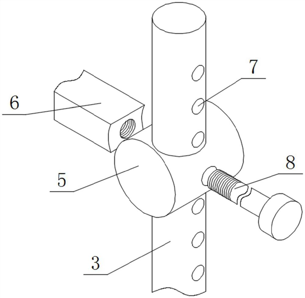
[0051] The outer surface of the column 3 is provided with a column-type sliding cylinder 5, one side of the outer wall of the column-type sliding cylinder 5 is installed with a fixing plate 6, and the outer wall of one side of the fixing plate 6 close to the column-shaped sliding cylinder 5 is provided with a connecting groove, and the outer wall of the column 3 is provided with a connecting groove. A plurality of sets of through grooves 7 arranged up and down are installed on the surface. A fastening rod 8 is installed through the outer wall of the side of the column-type sli...
Embodiment 2
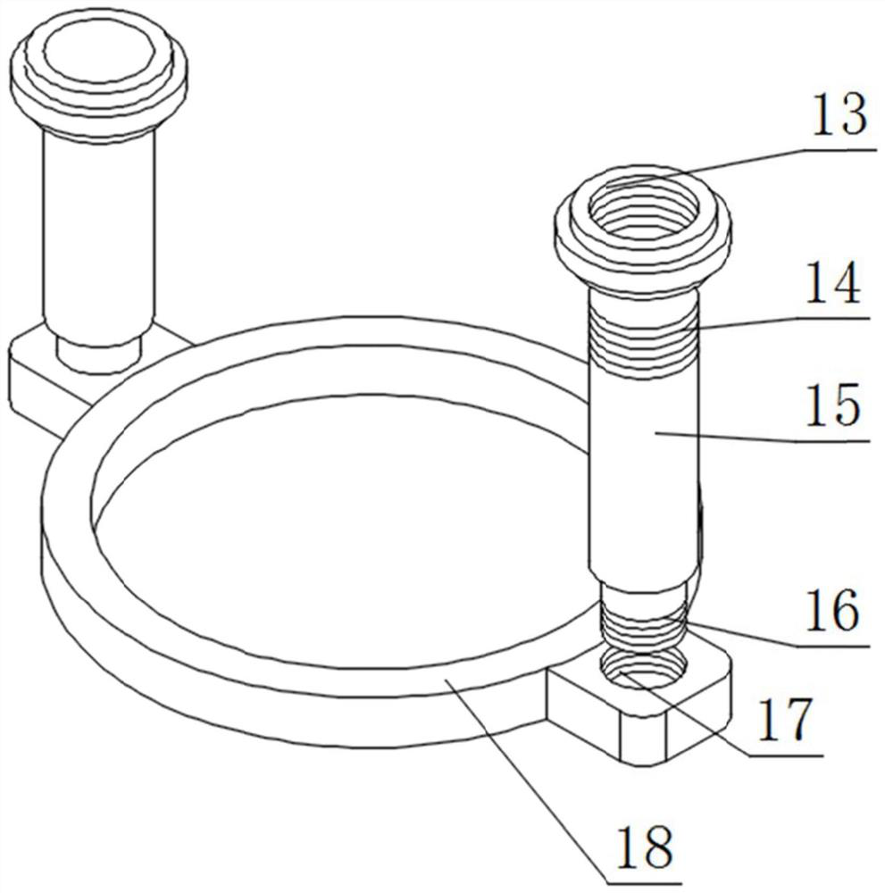
[0054] like figure 1 , image 3 , Figure 4 and Figure 5 As shown, a fixing ring 11 is installed on one side of the outer wall of the fixing plate 6, a square block 12 is installed on the outer wall of the side of the fixing ring 11 away from the fixing plate 6, and the tops of the fixing plate 6 and the square block 12 are provided with notches. A fitting swivel 13 is installed on the inner wall of the slot.
[0055] The inner walls of the two sets of fitting swivels 13 are fitted with connecting posts 14 through threaded fitting, the tops of the two sets of connecting posts 14 are both fitted with miniature electric push rods 15 , and the tops of the two sets of miniature electric push rods 15 are fitted with threaded discs 16. Combination blocks 17 are installed on the outer surfaces of the two groups of threaded discs 16, and a restriction ring 18 is installed on the outer wall of the adjacent side of the two groups of combination blocks 17. The bottom of the restricti...
Embodiment 3
[0058] like figure 1 , Image 6 and Figure 7As shown, a plurality of groups of evenly arranged vertical rods 20 are installed on the top of the restriction ring 18, a combined ring 21 is installed on the top of the plurality of vertical rods 20, an integrated plate 22 is installed on the back of the combined ring 21, and a top of the integrated plate 22 is installed with A top cover 24 is installed on the top of the electric telescopic rod 23 , the liquid collection bottle 19 , and a connecting long plate 25 is installed on the top of the electric telescopic rod 23 , and the bottom of the connecting long plate 25 is fitted with the top of the top cover 24 .
[0059] An annular steel plate 26 is installed on the inner wall of the top cover 24, a groove is arranged on the outer surface of the annular steel plate 26, a rubber collar 27 is installed on the inner wall of the groove, and a bottle stopper 28 is installed at the bottom of the liquid collection bottle 19, and the sto...
PUM
 Abstract
Description
Claims
Application Information
 - Generate Ideas
- Intellectual Property
- Life Sciences
- Materials
- Tech Scout
- Unparalleled Data Quality
- Higher Quality Content
- 60% Fewer Hallucinations
Browse by: Latest US Patents, China's latest patents, Technical Efficacy Thesaurus, Application Domain, Technology Topic, Popular Technical Reports.
© 2025 PatSnap. All rights reserved.Legal|Privacy policy|Modern Slavery Act Transparency Statement|Sitemap|About US| Contact US: help@patsnap.com