
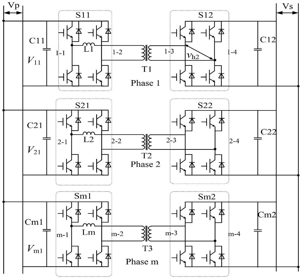
Multi-phase input-parallel output-parallel dual-active full-bridge converter and current-sharing control method

A full-bridge converter and dual-active technology, which is applied in the direction of DC power input conversion to DC power output, output power conversion device, control/regulation system, etc., can solve the problems of increasing system volume, weight and cost, and achieve Low cost, convenient implementation, and good current equalization effect

Pending Publication Date: 2022-05-27
NANJING UNIV OF AERONAUTICS & ASTRONAUTICS
View PDF0 Cites 0 Cited by
  • Summary
  • Abstract
  • Description
  • Claims
  • Application Information

AI Technical Summary

Problems solved by technology

However, the addition of coupled inductors also increases the size, weight and cost of the system

Method used


Image

  • Multi-phase input-parallel output-parallel dual-active full-bridge converter and current-sharing control method
  • Multi-phase input-parallel output-parallel dual-active full-bridge converter and current-sharing control method
  • Multi-phase input-parallel output-parallel dual-active full-bridge converter and current-sharing control method

Examples


Embodiment approach

[0057] As a specific implementation manner, the specific method of the step S1 is:

[0058] According to the transmission power expression of the dual active full-bridge converter, the output current equation of each sub-module is derived:

[0059]

[0060] of which: I 2i is the output current of the ith submodule; P i is the transmission power of the ith submodule; f si is the switching frequency of the ith submodule; n i is the turns ratio of the ith submodule; L i is the sum of the transformer leakage inductance and auxiliary inductance of the ith submodule; D 1i and D 2i are the inner and outer shift phase angles of the i-th submodule;

[0061] For the dual active full-bridge converter, it can be seen from (1) that there are two controllable variables in the output current expression of each sub-module, including: D 2i and f si ; When the circuit parameters of each sub-module do not match, it can be controlled on the basis of the common phase-shift control of th...

specific Embodiment approach

[0083] As a specific implementation manner, the specific method of the step S3 is:

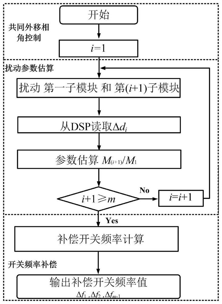
[0084] when M i / M 1 When obtained, from (4), it is known that each sub-module satisfies the switching frequency compensation value of the output current sharing, and further according to (2), the switching frequency of each sub-module is adjusted to realize the current sharing of the system

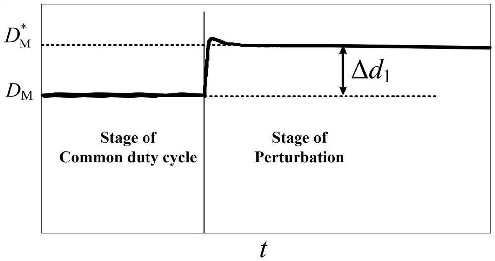
[0085] attached by image 3The simulation waveforms of the three-phase input parallel output parallel dual active full-bridge converter in the disturbance stage, it can be seen that the disturbance scheme that disturbs two sub-modules in turn and fixes the other sub-modules to move out is well implemented; Figure 4 and attached Figure 5 It can be seen that when the present invention is not adopted, the inductance current i of the three-phase input parallel output parallel dual active full-bridge converter L1 , i L2 , i L3 The simulation waveform of the inductor current is very different and unbal...


PUM


Abstract

The invention discloses an automatic current sharing method for a multi-phase input-parallel output-parallel dual-active bridge converter, and each sub-module in the multi-phase input-parallel output-parallel dual-active bridge converter is composed of a first switching circuit, a series inductor, an isolation transformer, a second switching circuit, and a DC port side capacitor. The parameter mismatching degree of each module is estimated through a cyclic disturbance parameter estimation algorithm, and once the parameters of each module are estimated, the compensation phase shift ratio of each sub-module of the parallel system meeting the current sharing can be calculated, so that the current sharing of the system is realized. According to the invention, automatic current sharing of the multi-phase input parallel output parallel dual-active bridge converter is realized, so that the power of each sub-module is distributed in a balanced manner; the high-power parallel switching power supply can be used for high-power parallel switching power supply occasions such as new energy power generation, electric automobiles, aerospace, uninterruptible power supplies, direct-current power distribution systems and energy storage systems, and has the advantages of reasonable method, convenience in implementation, good universality, small size, low cost and the like.

Description

technical field [0001] The invention relates to the technical field of power electronic cascade, in particular to a current sharing control method for multi-phase input parallel output parallel dual active full bridge converters. Background technique [0002] In recent years, converters in power electronic systems are developing towards high power, integration, low cost, high power density and high efficiency. The dual active bridge converter has many advantages such as power bidirectional transmission, electrical isolation, high transformation ratio buck-boost, easy to implement soft switching control, etc., and can realize multiple modular solutions through parallel combination, and has developed into new energy power generation, electric vehicles It is one of the core topologies of high-power parallel switching power supplies in aerospace, uninterruptible power supplies, DC power distribution systems, energy storage systems and other occasions. The modular parallel solut...

Claims


Application Information

Patent Timeline
Patent Type & Authority Applications(China)
IPC IPC(8): H02M3/335H02J1/10
CPCH02M3/3353H02J1/10
Inventor 孙志峰伍群芳王勤肖岚李金波
Owner NANJING UNIV OF AERONAUTICS & ASTRONAUTICS
Learn More