Deep sea natural gas hydrate strip partition mining method

A technology for zoned mining and natural gas, which is applied in the fields of mining fluid, earthwork drilling, climate sustainability, etc. It can solve the problems of low mining efficiency and achieve the effect of improving mining efficiency, clear design ideas, and stability and uniformity

Pending Publication Date: 2022-05-31
SHANDONG UNIV OF SCI & TECH
View PDF6 Cites 0 Cited by
  • Summary
  • Abstract
  • Description
  • Claims
  • Application Information

AI Technical Summary

Problems solved by technology

[0005] The purpose of the present invention is to provide a deep-sea natural gas hydrate strip mining method to solve the problem of low efficiency of natural gas hydrate production in sea areas and reduce the deformation of seabed formations caused by natural gas hydrate production, and to improve deep-sea natural gas hydrate production. efficiency

Method used


Image

  • Deep sea natural gas hydrate strip partition mining method
  • Deep sea natural gas hydrate strip partition mining method
  • Deep sea natural gas hydrate strip partition mining method

Examples


Embodiment 1

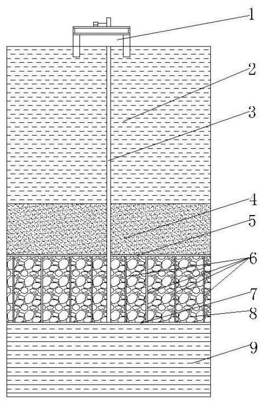
[0059] Analyze the formation permeability coefficient, formation temperature and particle gradation geological parameters in the area where the natural gas hydrate is located, determine the height of the seawater layer, the suitable position for the main vertical well 3, the thickness of the overburden layer 4, and the symmetrical length range of the strip mining area with respect to the main vertical well 3 ; The specific data is that the seawater depth is 800m, the overburden thickness is 200m, and the formation permeability coefficient is 1.5×10 -4 cm / s, formation pressure 12MPa, average particle size of formation particles 500μm;

[0060] Build the offshore production platform 1 and the main shaft 3 according to the above parameters; build the main shaft 3 through the overburden layer 4 to the height where the overburden layer 4 connects with the natural gas hydrate reservoir 8, and extend downward to the natural gas hydrate reservoir 8 ; According to the above parameters,...

Embodiment 2

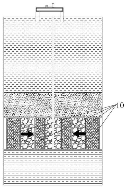
[0066] The only difference between this embodiment and the first embodiment is that, for example, image 3 , the mining method is a schematic diagram of advancing mining at intervals. First, the above-mentioned mining vertical well 6 is used to mine two mining strips on both sides of the main vertical well 3, and the horizontal well 7 for lowering the energy supplying strip is used to reduce the mining strip away from the main vertical well 3. The interior of the mining vertical well 6 side Fluid pressure, the natural gas generated by decomposition is transported to the offshore exploitation platform 1 through the upper recovery horizontal well 5 and the main vertical well 3 .

[0067] Further, when the productivity of the two mining strips on both sides of the main vertical shaft 3 is significantly reduced and cannot meet the commercial production requirements, the next operating mining strip is mined from the main vertical shaft 3 to the edge direction of the strip mining are...

Embodiment 3

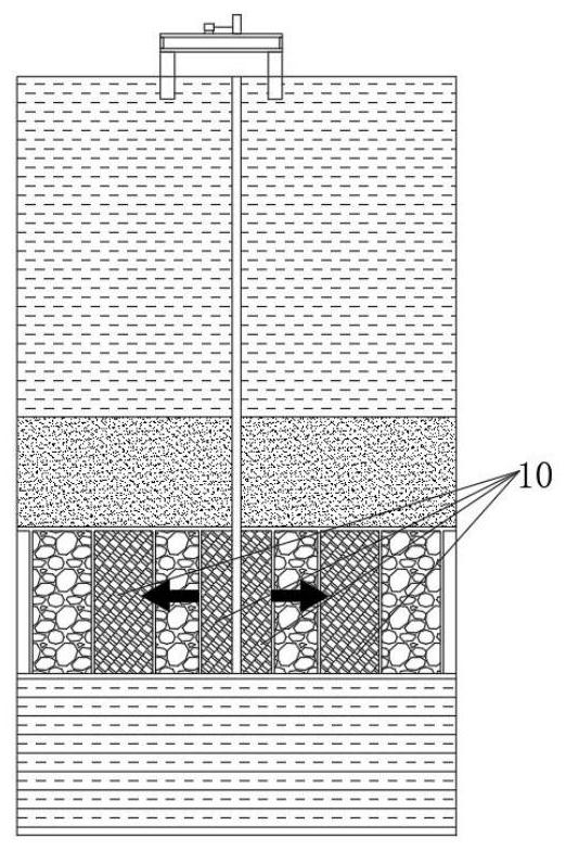
[0070] The only difference between this embodiment and the first embodiment is that, for example, Figure 4 , for the two sides to retreat in sequence at the same time; when the productivity of the two mining strips near the edge of the mining area is significantly reduced and cannot meet commercial mining, the mining strips are successively mined in the direction close to the vertical well 3 until the vertical well 3.

[0071] The difference between the effect of this embodiment and the first embodiment is that when the geological conditions of the mining area are good and the seabed stratum is relatively stable, the method of this example is used for mining. Relatively large, the economic benefits are obvious.


PUM


Abstract

The invention discloses a zoned mining method for deep-sea natural gas hydrate strips, which comprises the following steps of: establishing a strip mining area by taking a main force well as a center in a horizontal well and vertical well combined arrangement mode; the mining blocks on the two sides can be selected for simultaneous mining or single-side alternate mining according to the capacity requirement, and the mining blocks on the same side can also be selected for simultaneous mining or interval alternate mining according to the capacity requirement; the method is clear in design thought, the construction method is simple and easy to operate, the deep-sea natural gas hydrate exploitation efficiency can be effectively improved, and the single-well gas production efficiency is guaranteed.

Description

technical field [0001] The invention relates to a deep sea hydrate exploitation method, in particular to a deep sea natural gas hydrate strip zone exploitation method. Background technique [0002] Natural gas hydrate is an ice-like cage-like crystalline compound formed by natural gas and water at low temperature and high pressure. It is widely distributed in high-latitude polar permafrost formations and deep water formations such as ocean lakes. It has the characteristics of large reserves and high energy density. , considered as a potential energy source. Among them, the energy density of methane (the volume of methane per unit volume of rock under standard conditions) is very large, 10 times that of coal and black shale, and 2.5 times that of natural gas. [0003] Natural gas hydrates are widely distributed in continents, slopes of islands, uplifts of active and passive continental margins, polar continental shelves, and deep-water environments in oceans and some inland ...

Claims


Application Information

Patent Timeline
Patent Type & Authority Applications(China)
IPC IPC(8): E21B43/01E21B43/30E21B43/24
CPCE21B41/0099E21B43/01E21B43/305E21B43/24Y02P90/70
Inventor 公彬蒋宇静
Owner SHANDONG UNIV OF SCI & TECH
Why Eureka
Try Eureka