
Monochromator crystal orientation method

A crystal orientation, monochromator technology, applied in instruments, measuring devices, working accessories, etc., can solve the problems of unusable, easily damaged electric arc swing table, and harsh working environment, and achieve the effect of getting rid of dependence

Pending Publication Date: 2022-06-03
SHANGHAI INST OF APPLIED PHYSICS - CHINESE ACAD OF SCI
View PDF5 Cites 0 Cited by
  • Summary
  • Abstract
  • Description
  • Claims
  • Application Information

AI Technical Summary

Problems solved by technology

[0008] In the actual processing of the above steps, the corresponding rotating platform needs to work in the cutting fluid environment, the working environment is harsh, and the high-precision electric arc swing table is easily damaged and cannot be used.
However, the manual rotating platform usually only achieves a rotation accuracy of 12', which is unable to meet the high-precision orientation requirements of the monochromator crystal 1'.

Method used


Image

  • Monochromator crystal orientation method
  • Monochromator crystal orientation method
  • Monochromator crystal orientation method

Examples


Embodiment Construction

[0035] Below in conjunction with the accompanying drawings, preferred embodiments of the present invention are given and described in detail.

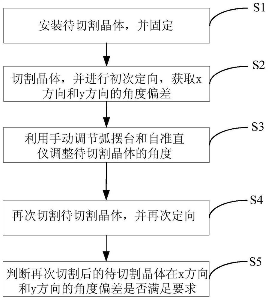
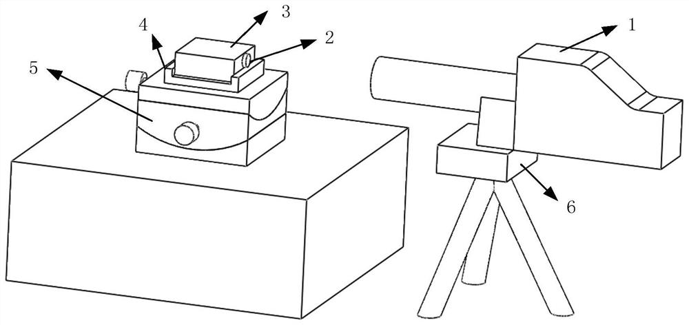
[0036] like figure 2 and image 3 As shown, the monochromator crystal orientation method provided by the present invention includes the following steps:

[0037] In step S1 , the crystal to be cut 3 is installed on the manually adjustable arc pendulum table 5 , and the crystal to be cut 3 is fixed by the crystal holder 4 . Specifically, step S1 includes:

[0038] In step S11 , the intergranular angle θ between the required crystal orientation of the crystal 3 to be cut and the known crystal orientation is calculated by means of the included angle of the crystal system.

[0039] Taking a single crystal silicon crystal as an example, the known crystal orientation is usually the crystal orientation of the end face of the single crystal silicon rod. At present, the crystal orientation of the end face of the single crystal silicon rod i...


PUM


Abstract

The invention relates to a color device crystal orientation method which comprises the following steps: S1, mounting a to-be-cut crystal on a manual adjustment arc swing table, and fixing the to-be-cut crystal; s2, the to-be-cut crystal is cut, the cut to-be-cut crystal is subjected to primary orientation, and the angular deviation of the cut to-be-cut crystal in the x direction and the y direction is obtained; s3, adjusting the angle of the to-be-cut crystal by utilizing a manual adjusting arc swinging table and an autocollimator; s4, after the angle of the to-be-cut crystal is adjusted, the to-be-cut crystal is cut again, the to-be-cut crystal cut again is oriented again, and the angle deviation of the to-be-cut crystal cut again in the x direction and the y direction is obtained; s5, judging whether the angular deviation of the to-be-cut crystal cut again in the x direction and the y direction is smaller than 1 'or not, and if yes, ending the step; and if not, repeating the steps S3 to S4.

Description

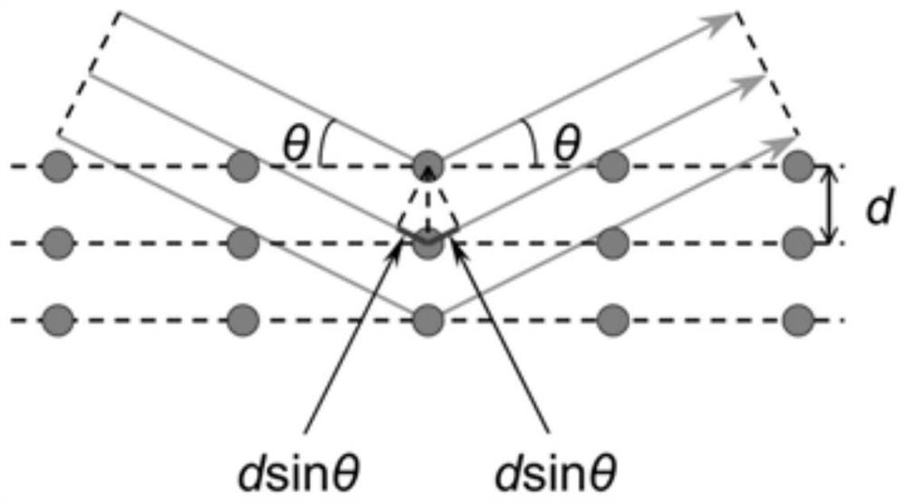
technical field [0001] The present invention relates to the field of synchrotron radiation beamlines, and more particularly to a monochromator crystal orientation method for synchrotron radiation beamlines. Background technique [0002] Synchrotron radiation is an excellent X-ray light source. It has the advantages of high collimation, high brightness, low divergence, and continuously adjustable wavelength. It has injected new life into X-ray spectroscopy, topography, structural analysis, crystal diffraction and other application fields. machine. Because the atomic layer spacing of a perfect crystal is of the same order of magnitude as the X-ray wavelength scale, X-ray monochromaticity can be achieved by separating the desired single-wavelength spectral line from the incident X-ray by using the crystal. A crystal that achieves a monochromatic function is commonly referred to as a monochromator crystal in synchrotron radiation. [0003] The monochromator crystal is the core...

Claims


Application Information

Patent Timeline
IPC IPC(8): B28D7/00B28D7/04B28D5/04G01B11/26
CPCB28D5/0058B28D5/0082B28D5/045G01B11/26Y02P40/57
Inventor 宋丽杨辉董晓浩
Owner SHANGHAI INST OF APPLIED PHYSICS - CHINESE ACAD OF SCI
Learn More