3D printer with double light spots and light spot switching method thereof

A 3D printer and double-spot technology, applied in 3D object support structures, manufacturing tools, processing data acquisition/processing, etc., can solve the problems of slow spot size switching speed, reduced processing accuracy, low efficiency, etc., and achieve fast switching speed, Improve accuracy and implement high-precision effects

Pending Publication Date: 2022-06-03
威斯坦(厦门)实业有限公司
View PDF0 Cites 0 Cited by
  • Summary
  • Abstract
  • Description
  • Claims
  • Application Information

AI Technical Summary

Problems solved by technology

However, this spot switching scheme uses a screw to drive the slider to move, and the screw usually has a positioning error during reciprocating motion, which reduces the machining accuracy; moreover, the screw movement takes a long time, resulting in slow speed and low efficiency of spot size switching

Method used


Image

  • 3D printer with double light spots and light spot switching method thereof
  • 3D printer with double light spots and light spot switching method thereof
  • 3D printer with double light spots and light spot switching method thereof

Examples


Embodiment 1

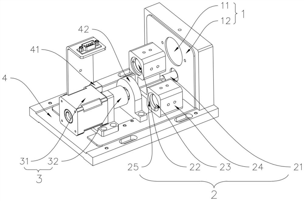
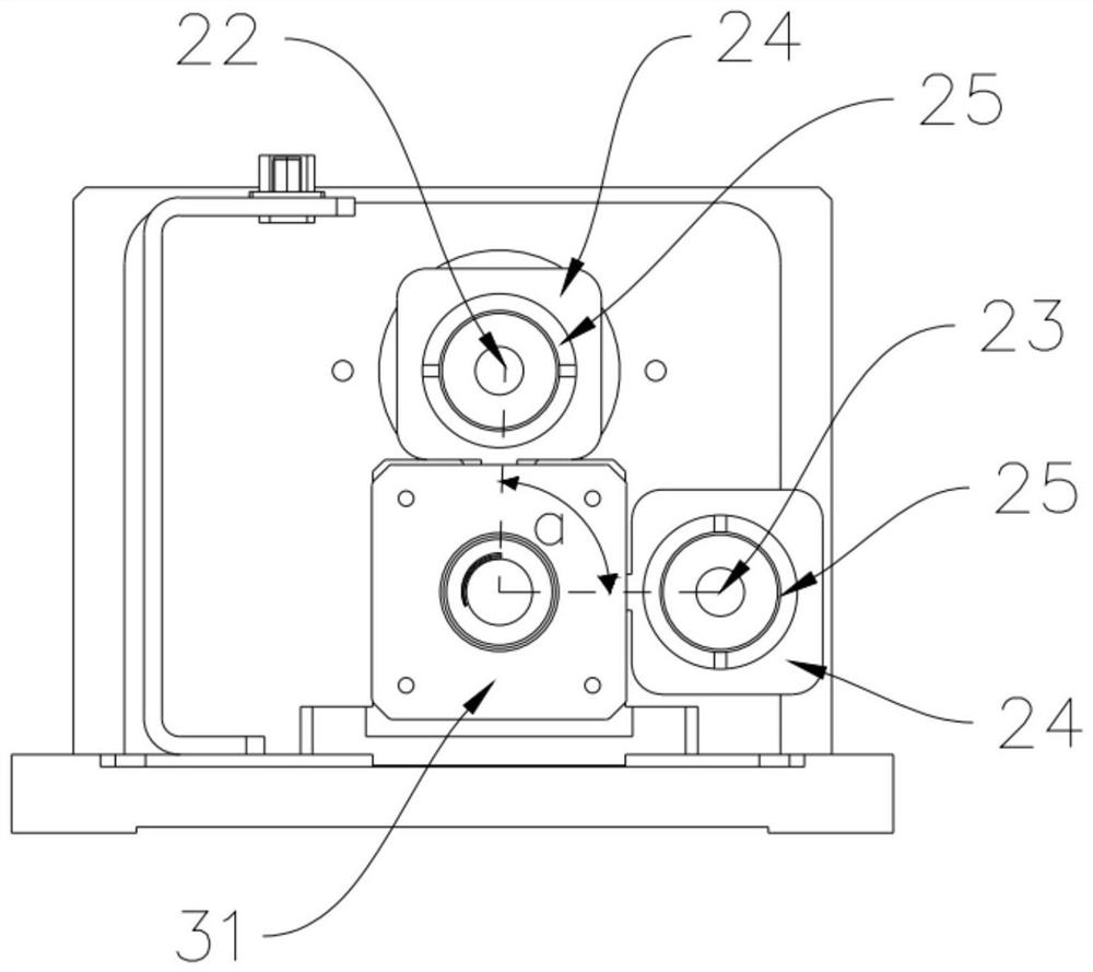
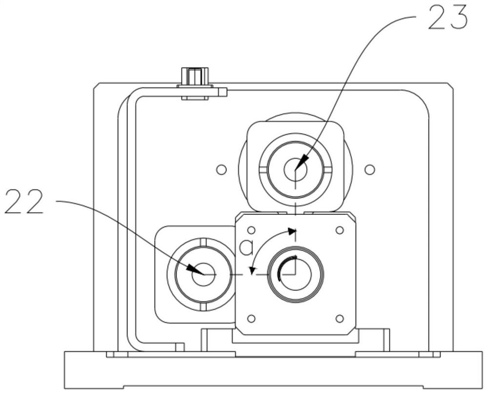
[0042] Please refer to Figure 1-5 , a 3D printer with double light spots, including a light spot adjustment mechanism arranged in the 3D printer, the light spot adjustment mechanism includes a stationary lens unit 1 and a movable lens unit 2 arranged oppositely, and a unit for driving the movable lens. Unit 2 rotates drive unit 3. The stationary lens unit 1 includes a fixed first optical lens 11 . The movable lens unit 2 includes a rotating shaft 21 and a second optical lens 22 and a third optical lens 23 fixedly arranged in the circumferential direction of the rotating shaft 21 . The first optical lens 11 , the second optical lens 22 and the The third optical lenses 23 are arranged at intervals along the axial direction of the rotating shaft 21 . When the second optical lens 22 and the first optical lens 11 are coaxial, it is the first position, and the first position is the first spot size; the third optical lens 23 and the first optical lens 11 When it is coaxial, it is...

Embodiment 2

[0050] Please refer to Image 6 , a light spot switching method using the above-mentioned 3D printer with dual light spots, comprising the following steps:

[0051] S01, setting light spot parameters, respectively setting the distances between the second optical lens 22 and the third optical lens 23 and the first optical lens 11 according to the light spot parameters of the 3D printer;

[0052] S02 , adjust the spot size, and rotate the rotating shaft 21 according to the spot size required for printing, so that the second optical lens 22 or the third optical lens 23 is concentric with the first optical lens 11 .

[0053] The setting of the light spot parameters includes selecting different lens curvatures and lens focal lengths according to the light spot parameters of the 3D printer. That is, the distance parameter from the first optical lens 11 can be adjusted by selecting the second optical lens 22 and the third optical lens 23 with different lens curvatures and lens focal...


PUM


Abstract

The invention relates to the technical field of 3D printers, in particular to a 3D printer with double light spots, which comprises a light spot adjusting mechanism arranged in the 3D printer, and the light spot adjusting mechanism comprises a static lens unit, a movable lens unit and a driving unit for driving the movable lens unit to rotate, and the static lens unit and the movable lens unit are oppositely arranged. The static lens unit comprises a first optical lens which is fixedly arranged. The movable lens unit comprises a rotating shaft, a second optical lens and a third optical lens, the second optical lens and the third optical lens are fixedly arranged in the circumferential direction of the rotating shaft, and the first optical lens, the second optical lens and the third optical lens are sequentially arranged at intervals in the axial direction of the rotating shaft. When the second optical lens and the first optical lens are coaxial, the position is a first position, and when the third optical lens and the first optical lens are coaxial, the position is a second position. The light spot adjusting mechanism provided by the invention is higher in light spot repeated positioning precision and higher in light spot switching efficiency.

Description

technical field [0001] The invention relates to the technical field of 3D printers, in particular to a 3D printer with dual light spots and a light spot switching method thereof. Background technique [0002] Light-curing 3D printing technology is the earliest practical rapid prototyping technology. The basic principle of this technology is to use the cumulative molding of materials to divide the shape of a three-dimensional target part into several plane layers, and scan the liquid photosensitive resin with a beam of a certain wavelength. , so that the scanned part of each layer of liquid photosensitive resin is cured and formed, and the parts not irradiated by the beam are still in liquid state, and finally each layer is accumulated to form the desired target parts. Among them, the spot mechanism is used to adjust the size of the emitted laser beam. [0003] At present, the size spot adjustment scheme usually used on the market is: first fix one convex lens lens, another ...

Claims


Application Information

Patent Timeline
IPC IPC(8): B29C64/124B29C64/277B29C64/393B33Y30/00B33Y50/02
CPCB29C64/124B29C64/277B29C64/393B33Y30/00B33Y50/02
Inventor 巫国宝
Owner 威斯坦(厦门)实业有限公司
Why Eureka
Try Eureka