
Large-scale structure and equipment installation method combined with laser scanning technology

A large-scale structure and equipment installation technology, applied in active optical measurement devices, measurement devices, surveying and navigation, etc., can solve problems such as difficulty in determining whether the processing results meet the requirements, difficulty in formulating and executing processing plans, and inability to obtain data, etc., to achieve Reduce the possibility of collision interference risk, eliminate the possibility of collision interference, and reduce the effect of lifting risk

Pending Publication Date: 2022-06-03
CHINA NUCLEAR IND 23 CONSTR
View PDF11 Cites 0 Cited by
  • Summary
  • Abstract
  • Description
  • Claims
  • Application Information

AI Technical Summary

Problems solved by technology

This method has the following disadvantages: the operation process is prone to cumulative errors, the longer the measurement distance, the greater the quantity, and the greater the error; the measurement work records and calculations are manual, and there are a large number of human error possibilities, which need to be repeated Checking, the process is operated by a number of personnel specially cooperating, which takes a long construction period; 100% of the data cannot be obtained, only some interference parts can be checked out, and the data can only be obtained from the locations that personnel can reach, and personnel cannot reach to perform operations The data of the parts cannot be obtained; the specific interference situation can only be fed back in a plane, which is not intuitive and three-dimensional, and it is very difficult to formulate and implement the treatment plan. At the same time, it is difficult to determine whether the treatment results meet the requirements after the treatment. less likely

Method used


Image

  • Large-scale structure and equipment installation method combined with laser scanning technology
  • Large-scale structure and equipment installation method combined with laser scanning technology
  • Large-scale structure and equipment installation method combined with laser scanning technology

Examples


Embodiment Construction

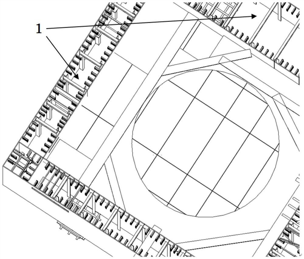
[0030] A large-scale structure and equipment installation method combined with laser scanning technology, including the following content,

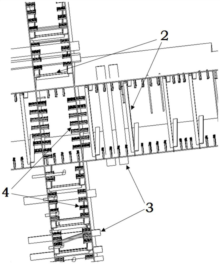
[0031] Step 1: According to the design drawings, the theoretical model of the large-scale building structure module and the theoretical model of the distribution of steel bars in the installation area can be established. After combining the two according to the theoretical size, the parts with a small safety distance can be sorted out as the follow-up investigation. focus.

[0032] The second step: formulate the scanning plan, determine the scanning route, arrange the scanning target point and the position of the target ball, and ensure the complete scanning to obtain the 3D point cloud data of the large building structure module body and the installation area.

[0033] Step 3: Use the measurement coordinate control network of the two areas to position the total station, collect the center coordinate data of the target point arranged duri...


PUM


Abstract

The invention belongs to large-scale equipment, and particularly relates to a large-scale structure and equipment installation method combined with a laser scanning technology. A large-scale structure and equipment installation method combined with a laser scanning technology comprises the following steps that firstly, key points are combed and checked; 2, formulating a scanning scheme; 3, collecting and combining data; 4, modeling is carried out; and 5, formulating a field treatment measure scheme. The method provided by the invention has the remarkable effects that the automation degree is high, the influence of manual operation on the result is small, the influence of field conditions is eliminated to a great extent by virtue of the non-contact data acquisition advantage of the laser scanning technology, and the model structure or the equipment body and the mounting area thereof can be subjected to live-action restoration; the point cloud data of all required parts can be obtained by 100% basically, the amount of point cloud data obtained through scanning is huge, and the fault tolerance is good.

Description

technical field [0001] The invention belongs to large-scale equipment, and in particular relates to a large-scale structure combined with laser scanning technology and an equipment installation method. Background technique [0002] Modular construction technology has been widely used in modern engineering construction. In construction engineering, there are a large number of situations where it is necessary to install very large structures or equipment in small or specific spaces. For example, in the construction of nuclear power plants, there are some building structure modules, which are large structures composed of multiple (groups) hollow steel plate walls. The hollow steel plate walls are generally composed of two steel plates connected by channel steel. The entire structural module After the assembly is completed, use a large crane to hoist it in place to the design position of the nuclear island. [0003] In order to make the large structure and equipment well combin...

Claims


Application Information

Patent Timeline
Patent Type & Authority Applications(China)
IPC IPC(8): G01C15/00
CPCG01C15/002Y02E30/30
Inventor 吴硕仲维光路宏杰吕宗遥王禄吕军翟志创彭贺祥
Owner CHINA NUCLEAR IND 23 CONSTR
Learn More