
Three-layer multi-beam luneberg lens antenna

A Lumber lens antenna and multi-beam technology, which is applied in the direction of antenna, antenna parts, antenna grounding switch structure connection, etc., can solve the problems of high processing cost, high cost, heavy weight, etc., and achieve improved antenna gain and low processing difficulty , the effect of strengthening the practical value

Pending Publication Date: 2022-06-03
CHENGDU PINNACLE MICROWAVE CO LTD
View PDF0 Cites 0 Cited by
  • Summary
  • Abstract
  • Description
  • Claims
  • Application Information

AI Technical Summary

Problems solved by technology

[0009] The above-mentioned first type of parallel plate waveguide type Luneberg lens is composed of two metal parallel plates, which leads to the inherent disadvantage of heavy weight of this type of lens antenna, which cannot achieve light weight
At the same time, filling the irregular-shaped medium in the parallel plate waveguide also brings complexity to the antenna processing, so it will also increase the corresponding cost and practicability
In addition, by arranging a large number of periodic metal columns to achieve a graded refractive index lens, this kind of lens can only be processed by a milling machine, and the cost is particularly high
The structure of the second type of metamaterial / metasurface Lunberg lens is relatively complex, which adds a lot of difficulty to the antenna design, and the processing cost is also high
However, at present, the more common Luneberg lens antennas with holes in the dielectric substrate are mostly single-layer structures, which have problems such as unsatisfactory antenna gain and small coverage of the antenna beam. Only by solving these problems can the This type of Lunberg lens antenna has better practical value

Method used


Image

  • Three-layer multi-beam luneberg lens antenna
  • Three-layer multi-beam luneberg lens antenna
  • Three-layer multi-beam luneberg lens antenna

Examples


specific Embodiment

[0039] see Figure 1-10 As shown, the specific embodiments provided by the present invention are as follows:

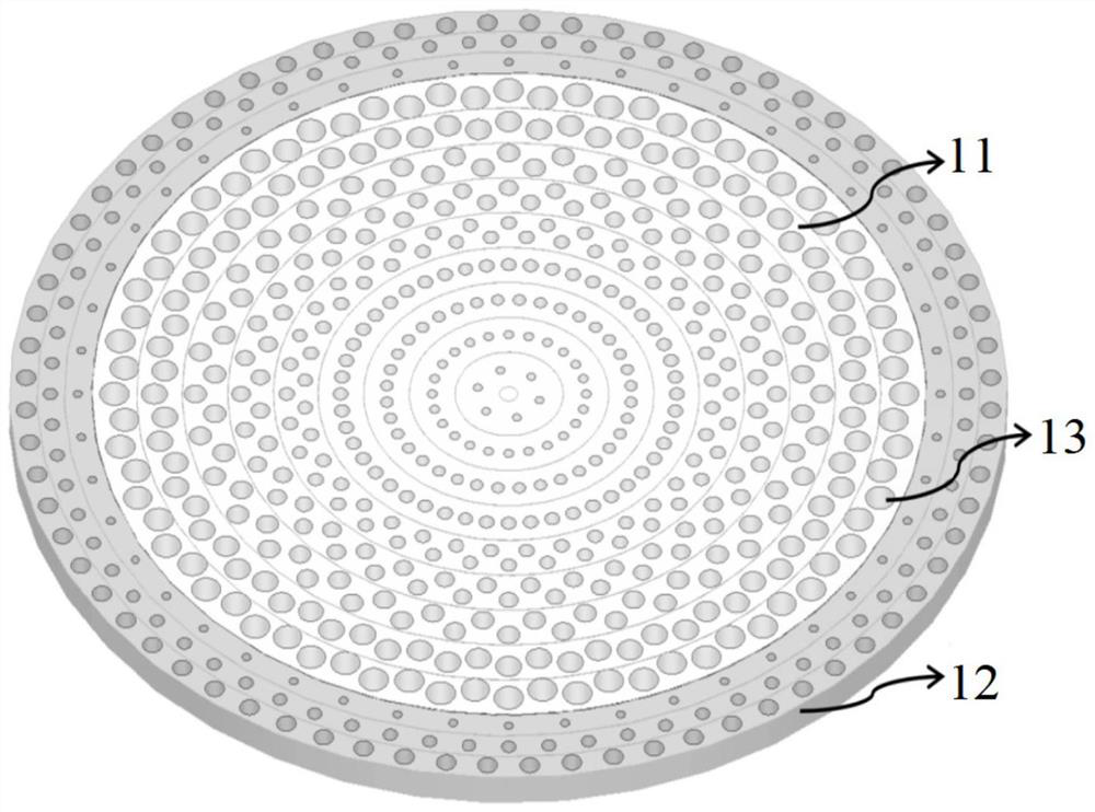
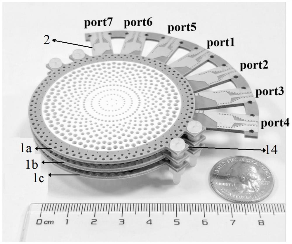
[0040] combine Figure 1-2 As shown in the figure, this embodiment provides a three-layer multi-beam Lunberg lens antenna, which includes a top dielectric substrate 1a, an intermediate layer dielectric substrate 1b and a bottom dielectric substrate 1c with the same structure. The three-layer dielectric substrate is in a direction perpendicular to the dielectric substrate. A parallel and spaced arrangement is formed; it can be understood that, in practical applications, in order to facilitate the fixing of each layer of dielectric substrates, at least one fixing part can be provided at the edge of each layer of the dielectric substrate, and the fixing part can be connected to the corresponding dielectric substrate. The substrates are connected as a whole, for example, as figure 2 As shown in the figure, the fixing part is set as a fixing ear 14 extending from one si...


PUM

PropertyMeasurementUnit
thicknessaaaaaaaaaa
relative permittivityaaaaaaaaaa

Abstract

The invention provides a three-layer multi-beam Luneberg lens antenna which comprises three layers of dielectric substrates with the same structure, and the three layers of dielectric substrates are arranged in parallel at intervals in the direction perpendicular to the dielectric substrates. Each layer of dielectric substrate comprises a cylindrical internal substrate and an annular external substrate nested at the periphery of the internal substrate, and a plurality of through holes are formed in the internal substrate and the external substrate, so that the effective dielectric constant of each layer of dielectric substrate is gradually reduced from the center to the outermost layer. The antenna provided by the invention adopts a three-layer lens structure, is light and handy in structure, low in processing cost and relatively high in gain, can better meet the multi-beam high-gain radiation requirement of a 5G millimeter wave frequency band, and has relatively high application value.

Description

technical field [0001] The invention relates to an antenna technology in a wireless communication system, in particular to a three-layer multi-beam Lumberg lens antenna. Background technique [0002] As the key component of the front end of the communication system, the performance of the antenna is directly related to the performance of the entire communication system. With the comprehensive advancement of wireless communication technologies represented by 5G and the Internet of Things, there is an urgent need to develop high-gain multi-beam antenna components suitable for their application scenarios. As an important branch of antennas, lens antennas are widely used in scenarios such as mobile communications, millimeter-wave communications, and satellite communications. [0003] In the millimeter wave and terahertz frequency bands, graded index lenses have excellent performance, among which Lumberg lens antennas are widely researched and applied. Lumberg lenses are usuall...

Claims


Application Information

Patent Timeline
Patent Type & Authority Applications(China)
IPC IPC(8): H01Q15/08H01Q19/06H01Q25/00H01Q1/50H01Q1/00
CPCH01Q15/08H01Q19/06H01Q1/002H01Q1/50H01Q25/002Y02D30/70
Inventor 董元旦王熙程洋王崭马增红
Owner CHENGDU PINNACLE MICROWAVE CO LTD
Learn More