Electrostatically-driven MEMS comb tooth structure, micromirror adopting structure and preparation method of micromirror

A technology of electrostatic drive and comb structure, which is applied in the field of micromirror and its preparation, electrostatically driven MEMS comb structure, can solve problems such as explosion and comb damage, and achieve the effect of simple process, preventive structure and small friction coefficient

Active Publication Date: 2022-06-07
XIAN CHISHINE OPTOELECTRONICS TECH CO LTD
View PDF5 Cites 1 Cited by
  • Summary
  • Abstract
  • Description
  • Claims
  • Application Information

AI Technical Summary

Problems solved by technology

Figure 1(b) shows that the driving comb 200 connected to the driving voltage Vd is tilted and is in contact with the grounding comb 100. Since there is no insulating layer on the surface of the two combs, the driving comb 200 and the grounding comb 100 are both conductive, and the resistance Very small, so in this state, the driving voltage is short-circuited with the ground wire, resulting in an instantaneous large current, high temperature or even sparks and local explosions in the contact area between the driving comb 200 and the grounding comb 100, resulting in damage to the comb

Method used


Image

  • Electrostatically-driven MEMS comb tooth structure, micromirror adopting structure and preparation method of micromirror
  • Electrostatically-driven MEMS comb tooth structure, micromirror adopting structure and preparation method of micromirror
  • Electrostatically-driven MEMS comb tooth structure, micromirror adopting structure and preparation method of micromirror

Examples


Embodiment Construction

[0049] The present invention is described in detail below in conjunction with the accompanying drawings.

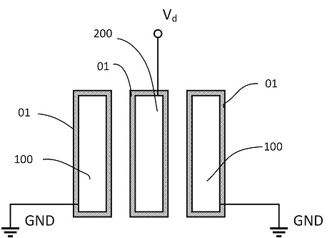
[0050] Electrostatic drive MEMS comb structure, the comb surface has an insulating layer 01, adjacent comb surface of the insulation layer is the same insulation layer or different insulation layer. Maintain a gap between the comb teeth under normal conditions, as shown in Figure 2(a).

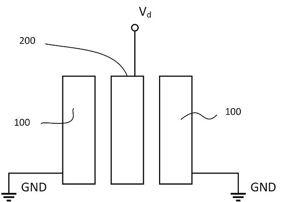
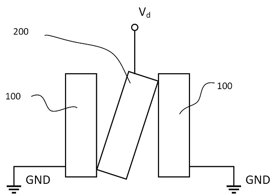
[0051]The electrostatic drive MEMS comb structure, comprising at least one set of drive comb teeth 200 and at least one set of ground comb teeth 100, wherein the drive comb is connected to drive voltage, grounding comb ground wire; The number of comb teeth for each group of drive combs and grounded combs is greater than or equal to 1; The drive comb group and the grounded comb group are staggered and arranged in the shape of a fork finger, that is, the two sides of each drive comb are grounded combs or no structure, and the two sides of each grounded comb are driven combs or no structure. Und...


PUM

PropertyMeasurementUnit
thicknessaaaaaaaaaa

Abstract

The invention discloses an electrostatic driving MEMS comb tooth structure, a micromirror adopting the structure and a preparation method of the micromirror. According to the electrostatic driving MEMS comb tooth structure, the surfaces of comb teeth are provided with insulating layers, and the insulating layers on the surfaces of the adjacent comb teeth are the same kind of insulating layers or different insulating layers; the micro-mirror adopting the electrostatic driving MEMS comb tooth structure is sequentially composed of a substrate, an isolation layer and a device layer from bottom to top. According to the manufacturing method of the micromirror, the insulating layer is manufactured by adopting a high-temperature oxidation method, a plasma enhanced chemical vapor deposition method, a low-pressure chemical vapor deposition method, a normal-pressure chemical vapor deposition method, a physical deposition method, an atomic layer deposition method or a step-by-step heterogeneous deposition method; the same or different insulating layers are obtained on the surfaces of the driving comb teeth and the surfaces of the grounding comb teeth; when the driving comb teeth and the grounding comb teeth generate adsorption, insulating layers on the surfaces of the two comb teeth are contacted, short circuit is not formed, and a good insulating effect is achieved. The electrostatic drive type MEMS micromirror capable of preventing adsorption damage is compact in structure and simple in process.

Description

Technical field [0001] The present invention relates to the field of MEMS technology of microelectromechanical systems, in particular to an electrostatic drive MEMS comb structure, a micromirror using this structure and a preparation method thereof. Background [0002] The comb structure of electrostatic drive is a class of micro-drive structures widely used in microelectromechanical system (MEMS) sensors, drivers and actuators. Electrostatic drive comb structure generally contains at least one set of drive comb teeth and a set of grounded comb teeth; The drive comb and grounded comb groups are staggered, in the shape of a fork finger, that is, each drive comb is adjacent to the ground comb, each grounded comb on both sides is the drive comb, and the adjacent comb teeth maintain a certain distance between each other, and do not contact each other. The drive comb group is connected to the drive voltage, the ground comb group is connected to the ground wire, and the relative displa...

Claims


Application Information

Patent Timeline
Patent Type & Authority Applications(China)
IPC IPC(8): G02B26/08C23C14/22C23C16/44C23C16/455C23C16/50B81B3/00B81B7/02B81C1/00
CPCG02B26/0841C23C14/22C23C16/44C23C16/50C23C16/45525B81B3/0002B81B3/0008B81B7/02B81C1/00134B81C1/00476B81C1/0096B81B2201/042
Inventor 姜军委张妮妮刘青峰马力杨涛彭磊李欢欢王芳
Owner XIAN CHISHINE OPTOELECTRONICS TECH CO LTD
Why Eureka
Try Eureka