
Device and method for preparing composite roller through electroslag remelting method of crystallizer additional magnetic field

A technology of electroslag remelting and composite rolls, which is applied in the field of metallurgical equipment, can solve problems such as excessive melting of the mandrel surface, reduction of roll quality and service life, dilution of cladding layer components, etc., to improve circumferential uniformity and shaft Good uniformity and surface quality

Pending Publication Date: 2022-06-24
NORTHEASTERN UNIV
View PDF10 Cites 0 Cited by
  • Summary
  • Abstract
  • Description
  • Claims
  • Application Information

AI Technical Summary

Problems solved by technology

The use of high-strength forged steel for the mandrel can effectively improve the strength and toughness of the roll mandrel and roll neck; however, the disadvantage of this method is that the equipment is complicated, the operation is difficult, and the production cost is high
The application of electroslag remelting method to prepare composite rolls also has obvious shortcomings; the current loop of traditional electroslag remelting method is the circuit of power supply-consumable electrode-slag pool-mandrel, and the mandrel is used as one pole, resulting in the mandrel Excessive melting of the surface leads to dilution of the cladding layer components, thereby reducing the mechanical properties of the cladding layer; at the beginning of the process, the mandrel fails to melt, the metallurgical bonding is poor, and the axial uniformity of the rolls throughout the process cycle is poor. The problem of poor axial uniformity of rolls, which eventually leads to reduced roll quality and service life

Method used


Image

  • Device and method for preparing composite roller through electroslag remelting method of crystallizer additional magnetic field
  • Device and method for preparing composite roller through electroslag remelting method of crystallizer additional magnetic field

Examples


Embodiment 1

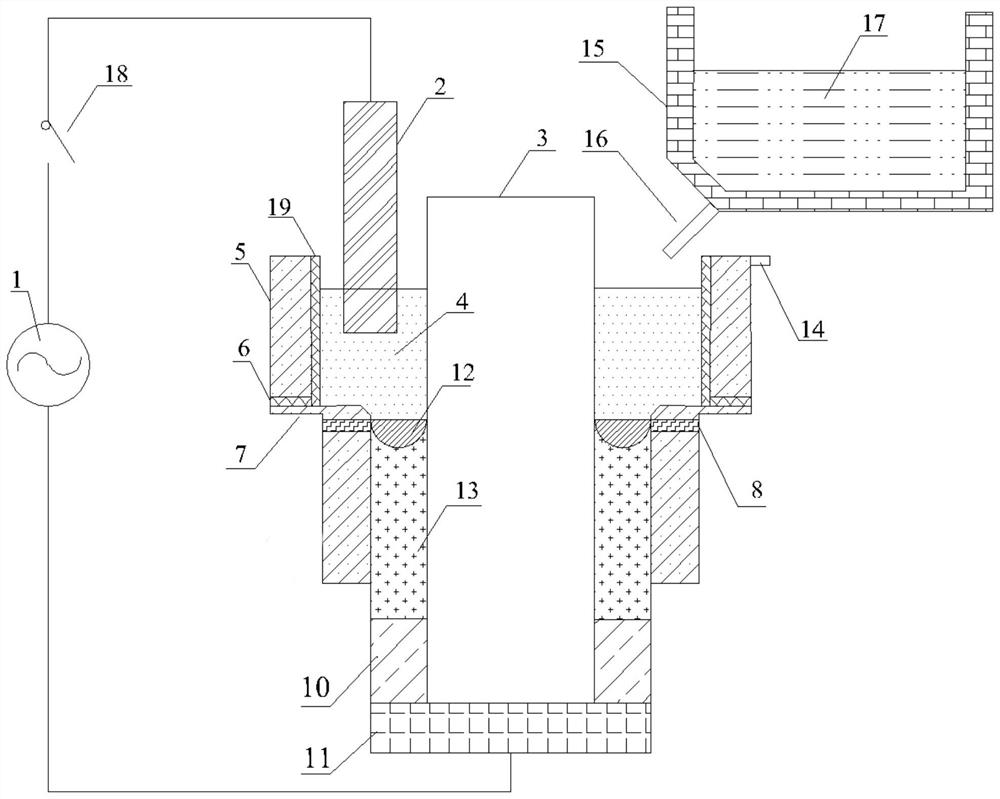
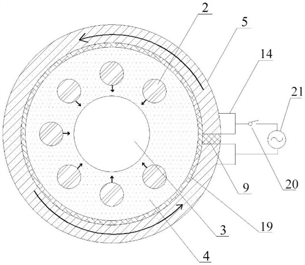
[0042] The structure of the device for preparing the composite roll by the electroslag remelting method with the additional magnetic field of the crystallizer is as follows figure 1 , the top view is as figure 2 As shown, it includes remelting power supply 1, mold power supply 21, dummy plate 11, upper mold 5 and lower mold 7; lower mold 7 is T-shaped, and upper mold 5 and lower mold 7 constitute electroslag Furnace crystallizer; The upper crystallizer 5 and the lower crystallizer 7 are separated by a ring-shaped insulating gasket 6;

[0043] The inner wall of the upper crystallizer 5 is covered with an insulating ring 19; the upper crystallizer 5 is provided with a gap, the gap runs through the top surface and the bottom surface of the upper crystallizer 5, and connects the inside and outside of the upper crystallizer 5, and the gap is filled with insulating blocks. 9;

[0044] One pole of the remelting power supply 1 is connected to the dummy plate 11, and the other pole ...

Embodiment 2

[0057] The structure of the device is the same as that of Embodiment 1, and the difference lies in:

[0058] The projection of the axes of the two liquid level detection probes 8 on the horizontal plane forms an included angle θ; the included angle θ is 90°;

[0059] The method is the same as in Example 1, except that:

[0060] When the mold power is turned on, the current in the mold loop is 1000A; the temperature of the slag pool is still unevenly distributed along the circumferential direction during the thermal process. In the process of cladding and compounding, the surface of the mandrel melts unevenly, the temperature near the graphite electrode is high, the surface of the mandrel melts faster and the depth is deeper; the temperature away from the electrode and the casting point is low, and the surface of the mandrel melts slowly. , the depth is shallow, and the overall composite effect of the roll circumferential direction is still poor.

Embodiment 3

[0062] The structure of the device is the same as that of Embodiment 1, and the difference lies in:

[0063] The projection of the axes of the two liquid level detection probes 8 on the horizontal plane forms an included angle θ; the included angle θ is 180゜;

[0064] The method is the same as in Example 1, except that:

[0065] When the power of the mold is turned on, the current in the mold loop is 5000A; the slag pool rotates counterclockwise during the preheating process and the cladding composite process, which greatly improves the distribution of the temperature field. In the process of cladding and recombination, the circumferential flow promotes the heat transfer of the circumferential flow, and promotes the uniform melting of the mandrel surface and the metallurgical bonding process of the composite interface. The process was successfully completed and the interface bonding quality was good.


PUM


Abstract

The invention discloses a device and a method for preparing a composite roller by an electroslag remelting method of a crystallizer additional magnetic field. The device comprises a remelting power supply, a crystallizer power supply, a dummy ingot plate, an upper crystallizer and a lower crystallizer, a notch is formed in the upper crystallizer and is filled with an insulating block; two conductive interfaces are assembled on the upper portion of the outer wall of the upper crystallizer, located on the two sides of the insulating block and connected with the two electrodes of a crystallizer power source respectively. The method comprises the following steps: (1) placing the mandrel in an electroslag furnace crystallizer; (2) arranging a coating layer; (3) putting the ladle molten pool into an electroslag furnace crystallizer to form a liquid slag pool; (4) descending the consumable electrode to a liquid slag pool; the remelting switch is switched on; (5) connecting two conductive interfaces with two electrodes of a crystallizer power supply; and (6) starting an ingot pulling system. A conductive loop in the crystallizer is additionally arranged in the composite system, and the temperature field of a slag bath, especially the temperature field near a slag-metal interface, is reasonably optimized by adding an axial extra magnetic field in a remelting composite area.

Description

technical field [0001] The invention belongs to the technical field of metallurgical equipment, and particularly relates to a device and method for preparing a composite roll by an electroslag remelting method with an additional magnetic field of a crystallizer. Background technique [0002] The most commonly used composite casting rolls mainly have the following methods: centrifugal casting method, continuous casting composite casting method (CPC), electroslag remelting method. The horizontal centrifugal casting method first pours the high alloy working layer. After the working layer is poured on the centrifuge, the mold is placed vertically, and then the core ductile iron is poured; the working layer of the composite roll is usually high alloy content. High chromium steel or High-speed steel, the core is ductile iron with good toughness; Nippon Steel Corporation of Japan has developed a continuous casting outer layer forming method to prepare a high-speed steel composite r...

Claims


Application Information

Patent Timeline
IPC IPC(8): B22D23/10B22D19/16
CPCB22D23/10B22D19/16
Inventor 董艳伍胡志豪姜周华侯志文邹涛王永王琪
Owner NORTHEASTERN UNIV
Learn More