
Controllable separated power device and swing piece manual-automatic integrated actuator

A technology of power device and power input end, applied in the field of mechanical automation, can solve the problems of tooth punching or manual automatic function switching delay, difficult separation or meshing between electromagnetic claw and planetary gear assembly, etc., to achieve smooth switching, low working energy consumption, Space and cost saving effect

Pending Publication Date: 2022-06-24
OECHSLER PLASTIC PROD TAICANG
View PDF1 Cites 0 Cited by
  • Summary
  • Abstract
  • Description
  • Claims
  • Application Information

AI Technical Summary

Problems solved by technology

[0003] Taking the Chinese invention patent with the publication number CN108316802A as an example, the patent discloses a manually operated electric opening and closing actuator for revolving doors. However, when the structure is interchanged between the electric mode and the manual mode at high speeds, it may be difficult to separate or engage the electromagnetic claw and the planetary gear assembly, which will lead to delays in gearing or manual function switching

Method used


Image

  • Controllable separated power device and swing piece manual-automatic integrated actuator
  • Controllable separated power device and swing piece manual-automatic integrated actuator
  • Controllable separated power device and swing piece manual-automatic integrated actuator

Examples


Embodiment 1

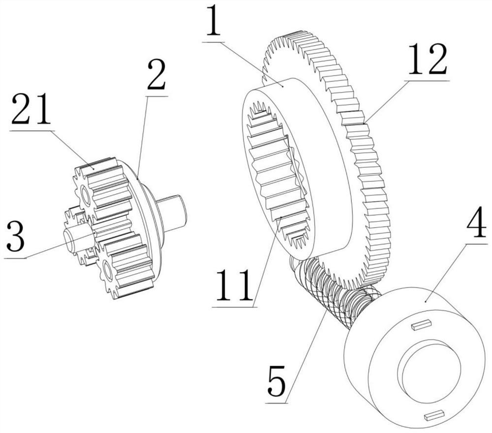
[0029] A controllable separation powerplant such as figure 1 As shown, it includes a ring gear 1, a planetary carrier 2 and a sun gear 3 that are rotatably arranged on the same axis; The inner ring gear part 11 on the inner circumference of the ring gear 1 is meshed, and the sun gear 3 is meshed with the planetary gear 21; The outer ring gear part 12 on the outer circumference of the ring gear 1 is non-self-locking meshing connection; in the planet carrier 2 and the sun gear 3, one end is used as the power input end, the other end is used as the power output end, and the locked-rotor motor 4 is used as the control end to control the ring gear 1. Whether it can rotate freely, so as to controllably switch whether the power input end and the power output end are in a power separation state or a power connection state.

[0030] The tooth shape of the outer ring gear part 12 is helical teeth or worm teeth. In order to ensure the non-self-locking meshing of the locked-rotor worm 5 ...

Embodiment 2

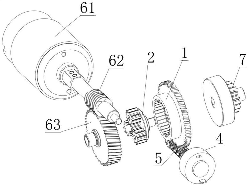
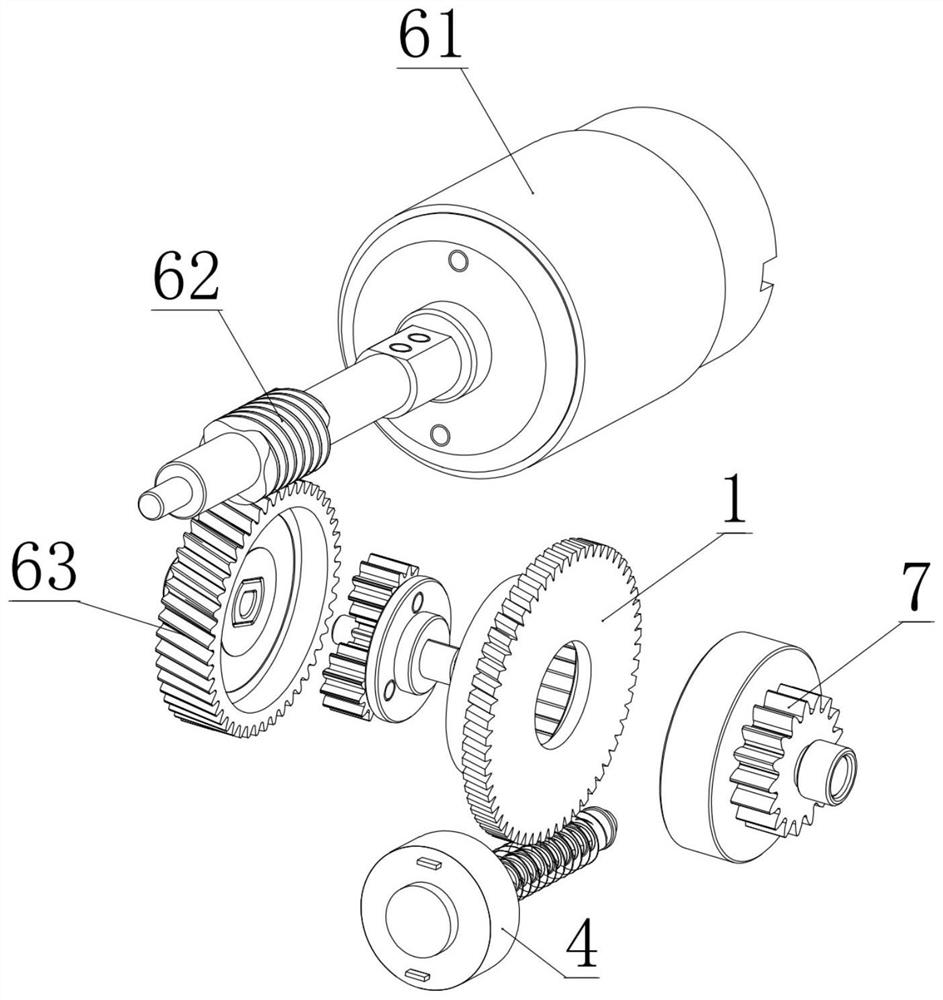
[0036] The controllable separation power plant provided in this embodiment is a further improvement to Embodiment 1, specifically as follows figure 2 , 3 As shown, the sun gear 3 is used as a power input end, and the planet carrier 2 is used as a power output end; a power supply unit is also provided at the power input end to drive the sun gear 3 to rotate. The power supply unit includes a power motor 61 , a power worm 62 driven to rotate by the power motor 61 , and a power gear 63 coaxially connected to the sun gear 3 ; the power worm 62 meshes with the power gear 63 . Among them, the power gear 63 is a worm gear or a helical gear. In addition, the planet carrier 2 is also coaxially connected with a power output gear 7 for external power output.

Embodiment 3

[0038] An oscillating piece manual-integrated actuator, such as Figure 4 As shown, it includes the controllable separation power device of Embodiment 2, and also includes an arc-shaped rack 91 and a limit post 92 . The inner side of the arc-shaped rack 91 has a tooth surface and meshes with the power output gear 7; the limit post 92 is arranged on the outer side of the arc-shaped rack 91 and abuts against the arc-shaped rack 91 to ensure that the arc-shaped rack 91 and the power output The gear 7 is meshed; the preferred way is to set a rolling sleeve on the limit post 92 to reduce the frictional force when the arc-shaped rack 91 moves; the power output gear 7 drives the arc-shaped rack 91 between the power output gear 7 and the limiter. move within the gaps between the bit posts 92 .

[0039] The manual-automatic actuator of the swing piece also includes a mounting bracket 93 ; the mounting bracket 93 is hinged on one end of the arc-shaped rack 91 .

[0040] The oscillatin...


PUM


Abstract

The invention belongs to the technical field of mechanical automation, and particularly relates to a power device and swing piece manual-automatic integrated actuator capable of being controlled to be separated. The controllable separation power device comprises a gear ring, a planet carrier and a sun gear which are rotatably arranged on the same axis. A group of planet gears arranged around the rotation axis of the planet carrier are mounted on the planet carrier, the planet gears are meshed with an inner gear ring part arranged on the inner circumference of the gear ring, and the sun gear is meshed with the planet gears; the power device further comprises a locked-rotor motor and a locked-rotor worm driven by the locked-rotor motor, and the locked-rotor worm is in non-self-locking meshing connection with an outer gear ring part arranged on the periphery of the gear ring. According to the separation-controllable power device, switching between the power separation state and the power connection state can be achieved by controlling the locked-rotor motor to be powered on or powered off, mechanical clutch is not involved in the switching process, and switching is quite quiet and smooth. And the whole structure is light, working energy consumption is low, and space and cost are saved.

Description

technical field [0001] The invention belongs to the technical field of mechanical automation, and in particular relates to a controllable and separable power device and a manual-integrated actuator of a pendulum member. Background technique [0002] There are a large number of rotatable and swingable parts in smart home and home appliances, such as glass windows, refrigerator doors, and rotating shelves. In order for these components to be both automatic and compatible with manual operating habits, actuators with power split capabilities are required. Such actuators usually have large installation size and complex structure, including multi-stage gear transmission mechanism and clutch device. Among them, the clutch device is the core component that realizes the mutual switching between the two states of power separation and power connection. At present, there are mainly electromagnetic clutch devices and mechanical clutch devices. The electromagnetic clutch device has stab...

Claims


Application Information

Patent Timeline
IPC IPC(8): F16H3/70F16D28/00F16H37/04F16H19/08H02K7/116F25D23/02E05F15/614E05F15/70E05F11/54
CPCF16H3/70F16H37/046F16H19/08F16D28/00H02K7/1166F25D23/028E05F15/614E05F15/70E05F11/54F16H2003/445F16H2003/447E05Y2201/216E05Y2900/31E05Y2201/676E05Y2400/32E05Y2201/72E05Y2201/248E05Y2201/71E05Y2201/704E05Y2201/726E05Y2400/3013
Inventor 周飞付政芮正国
Owner OECHSLER PLASTIC PROD TAICANG
Learn More