Divider driving synchronous reciprocating motion device

A reciprocating motion and divider technology, applied in printing, printing machines, rotary printing machines, etc., can solve problems such as the inability to meet small batches of rapid customization, complex belt drive structure, and limited configuration angles, and achieve small movement range, The effect of low mechanical noise and avoiding distortion

Pending Publication Date: 2022-06-28
SUZHOU CAI MACHINE
View PDF0 Cites 0 Cited by
  • Summary
  • Abstract
  • Description
  • Claims
  • Application Information

AI Technical Summary

Problems solved by technology

[0005] For the above two problems, most modern printing equipment use a belt-driven cup pressing device to solve the problem, but the structure of the belt drive is complex, the structural components are large, and the configuration angle is limited.
[0006] 3. Changes in cup materials: Paper cups have been used in the market now, but the traditional paper cup surface packaging pattern is flat-printed before forming. With consumption upgrading and product iteration speeding up, it is obvious that the traditional paper cup surface printing method exists. The drawback is that it cannot meet the needs of small batches of rapid customization. Customized paper cup printing needs to ensure that the printing pattern and the joint position of the paper cup are fixed. This is a new application research and development direction for cup printing machines.

Method used


Image

  • Divider driving synchronous reciprocating motion device
  • Divider driving synchronous reciprocating motion device
  • Divider driving synchronous reciprocating motion device

Examples


Embodiment Construction

[0017] In order to make the purpose, technical solutions and advantages of the embodiments of the present invention clearer, the technical solutions in the embodiments of the present invention will be clearly and completely described below in conjunction with the drawings in the embodiments of the present invention. Obviously, the described embodiments It is a part of embodiments of the present invention, but not all embodiments. Based on the embodiments of the present invention, all other embodiments obtained by persons of ordinary skill in the art without creative efforts fall within the protection scope of the present invention.

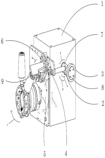
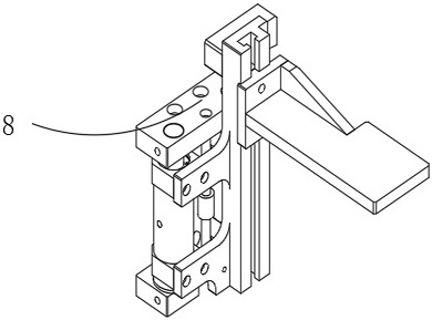
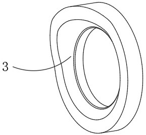
[0018] see Figure 1-3 : A splitter 1 drives a synchronous reciprocating motion device, including a splitter 1, an active rocker 2, a driving cam 3 on the power source end face of the reciprocating motion device, a driven rocker 4, a transfer connecting rod 5 and a reciprocating sliding assembly 6, reciprocating The drive cam 3 on the end face of...


PUM


Abstract

The invention relates to the technical field of plastic cup and formed paper cup printing machines, and discloses a divider-driven synchronous reciprocating motion device, a power source end face driving cam of the reciprocating motion device and a divider share a force input shaft, power is transmitted to a driven rocker through a driving rocker, and then motion is transmitted to a reciprocating motion assembly. Belt transmission used by an old-fashioned cup jacking device is abandoned, a rocker transmission structure is used, the transmission structure is simplified, the limitation of the transmission direction of belt transmission power is eliminated, and two or more reciprocating motion devices are driven to move synchronously by a reciprocating motion device power source end face driving cam at the same time. A power source end face driving cam of the reciprocating motion device drives the cup pressing device to move downwards to start to be combined with a cup in the return stroke stage, when the reciprocating motion device is arranged at the three o'clock position of a divider output shaft, an unpowered rotating wheel is arranged, cup pressing is kept in the stop stage, and distortion of printed patterns is effectively avoided.

Description

technical field [0001] The invention relates to the technical field of printing machines for plastic cups and formed paper cups, in particular to a divider-driven synchronous reciprocating motion device. Background technique [0002] Now the fast-moving consumer beverage packaging industry is dominated by plastic cups. With the gradual development of the market and changes in demand, many new cup types continue to emerge. New packaging materials are being tried and applied. Inadequacies and defects of printing equipment are exposed. [0003] 1. For the change of cup shape: more tall cups and large taper cups appear on the market. The printed pattern surrounds the cup for a week. The unfolded view is a fan shape, and the unfolded view of the printing cylinder is rectangular. In order to ensure that the printed pattern is complete and not distorted, Modern printing equipment makes up for the elastic-plastic deformation of the transfer rubber, but in the actual printing proces...

Claims


Application Information

Patent Timeline
Patent Type & Authority Applications(China)
IPC IPC(8): B41F17/14B41F17/00
CPCB41F17/14B41F17/00
Inventor 王福振肖治国
Owner SUZHOU CAI MACHINE
Why Eureka
Try Eureka