Static pressure suspension piston type hydraulic breaking hammer

A hydraulic breaker and piston technology, applied in construction, earth mover/excavator, etc., can solve the problems of no support, reduce the mechanical strength of the piston, and inconvenient cleaning and maintenance

Pending Publication Date: 2022-07-01
赵德朝
View PDF2 Cites 2 Cited by
  • Summary
  • Abstract
  • Description
  • Claims
  • Application Information

AI Technical Summary

Problems solved by technology

Existing problems: 1. During the reciprocating movement of the piston, when the maximum diameter of the piston close to the head will block the return oil of the 4 oil chambers at the maximum diameter (the section near the tail) (that is, the cylinder and a2 The annular oil groove connected to the port is closed), resulting in no support at this stage
2. During the reciprocating movement of the piston, when the four oil chambers at the maximum diameter of the piston (a section near the tail) communicate with the annular oil groove in the cylinder body that communicates with the a2 or a3 port, there is no support at this stage
3. Since there are 4 oil chamber supports on the piston head and 4 oil chamber supports on the maximum diameter of the piston, each of the 4 oil chambers will generate hydraulic pressure in 4 directions on the cylinder, resulting in deformation of the cylinder. The gap between the cylinder and the cylinder is sealed (the fit gap is small), and the deformation of the cylinder will cause the piston to be locked and damaged, that is, the cylinder will be pulled
If you want to reduce the deformation, you will inevitably increase the structural size and weight of the cylinder, and you need a large-tonnage main engine to match it. Without increasing the work efficiency, increasing the tonnage of the main engine will waste resources
4. The piston is equipped with axial oil passage, radial oil passage, oil chamber, etc., which reduces the mechanical strength of the piston, but the reciprocating movement of the piston hits the drill rod, which is subject to great impact and is easily damaged
5. The axial oil passage and the radial oil passage on the piston are all elongated holes, which are difficult to process, low in efficiency, and inconvenient for cleaning and maintenance
Existing problems: 1. During the reciprocating movement of the piston, when the piston is close to the head of a section of the largest diameter (front oil groove), the valve will return the oil to the four oil chambers between the annular groove and the upper chamber (alias: rear chamber) The oil return of the cylinder is blocked (that is, the annular oil groove connected to the a2 port in the cylinder is closed), resulting in no support at this stage
2. During the reciprocating movement of the piston, when the four oil chambers between the valve-controlled oil return annular groove and the upper chamber (alias: rear chamber) communicate with the piston axial unloading groove and the piston annular unloading groove, the stage unsupported
3. Since there are 4 oil chamber supports on the piston head and 4 oil chamber supports on the maximum diameter of the piston, each of the 4 oil chambers will generate hydraulic pressure in 4 directions on the cylinder, resulting in deformation of the cylinder. The gap between the cylinder and the cylinder is sealed (the fit gap is small), and the deformation of the cylinder will cause the piston to be locked and damaged, that is, the cylinder will be pulled
If you want to reduce the deformation, you will inevitably increase the structural size and weight of the cylinder, and you need a large-tonnage main engine to match it. Without increasing the work efficiency, increasing the tonnage of the main engine will waste resources
4. The four oil cavities between the valve-controlled oil return annular groove and the upper cavity (alias: rear cavity) need to be processed with a tool with a long cantilever, which has low efficiency and poor precision
5. Each oil chamber supported by the piston requires oil supply through a slender hole, which is difficult to process, low in efficiency, and inconvenient for cleaning and maintenance

Method used


Image

  • Static pressure suspension piston type hydraulic breaking hammer
  • Static pressure suspension piston type hydraulic breaking hammer
  • Static pressure suspension piston type hydraulic breaking hammer

Examples


Embodiment 1

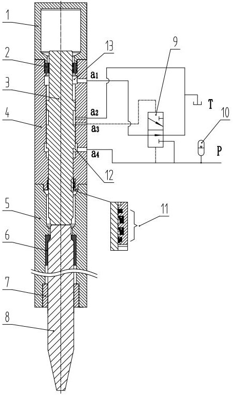
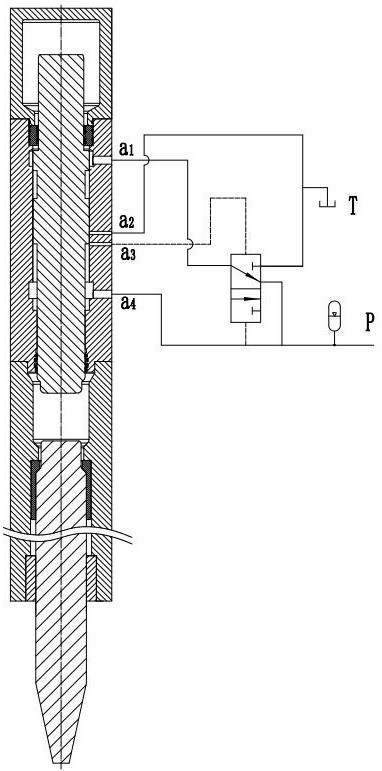
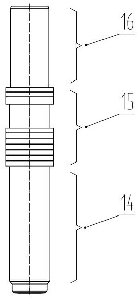
[0052] This embodiment mainly includes: a piston 3 and a cylinder 4 . The piston 3 reciprocates in the cylinder 4 . In the area where the cylinder block 4 and the head 14 of the piston 3 are matched (between the front chamber 12 and the main seal 11 ), two circles are provided with three static pressure suspension chambers 18 evenly distributed in each circle to support the piston 3 .

Embodiment 2

[0054] This embodiment mainly includes: a piston 3 and a cylinder 4 . The piston 3 reciprocates in the cylinder 4 . In the area where the cylinder 4 and the head 14 of the piston 3 are matched (between the front chamber 12 and the main seal 11 ), two circles with four static pressure suspension chambers 18 are evenly distributed in each circle to support the piston 3 .

Embodiment 3

[0056] This embodiment mainly includes: a piston 3 and a cylinder 4 . The piston 3 reciprocates in the cylinder 4 . In the area where the cylinder 4 and the head 14 of the piston 3 are matched (between the front chamber 12 and the main seal 11 ), three circles, each of which is evenly distributed with three hydrostatic suspension chambers 18 , are used to support the piston 3 .


PUM


Abstract

The invention discloses a static pressure suspension piston type hydraulic breaking hammer which comprises a piston, a cylinder body, a drill rod seat, an inner sleeve, an outer sleeve and a drill rod. The piston reciprocates in the cylinder body to strike the drill rod; a drill rod for crushing rocks, an inner sleeve and an outer sleeve are arranged in the drill rod seat, wherein the inner sleeve and the outer sleeve play a guiding role, and meanwhile the inner sleeve and the outer sleeve have the effect of protecting the drill rod seat from being abraded. More than or equal to two circles are arranged in the area where the cylinder body is matched with the head of the piston, and more than two static pressure suspension cavities are evenly distributed in each circle and used for supporting the piston. The piston floats in the cylinder body through the static pressure suspension bearing, it is guaranteed that the matching faces of the piston and the cylinder body are separated by hydraulic oil when the piston is under a certain load and at any speed, and contact and strain are avoided.

Description

technical field [0001] The invention relates to a construction machinery attachment, in particular to a hydrostatic suspension piston type hydraulic breaker. Background technique [0002] Hydraulic breaker is an impact tool that converts hydraulic energy into mechanical energy. There are two basic moving elements—piston and reversing valve. At the beginning and end of each stroke, the piston realizes the reversal of the spool by opening or closing the control oil circuit of the reversing valve, and this cycle works. The basic working principle of the hydraulic breaker is: through the feedback control of the piston and the spool, the piston can be rapidly reciprocated under the driving of hydraulic pressure or hydraulic and pneumatic pressure, and the drill rod can be hit to do external work. [0003] For breaking stone, concrete and other construction materials, hydraulic breakers can be attached to various machines such as excavators, backhoes or other similar machines. T...

Claims


Application Information

Patent Timeline
Patent Type & Authority Applications(China)
IPC IPC(8): E02F5/30E02F9/22
CPCE02F5/30E02F9/2264E02F9/2267
Inventor 赵德朝
Owner 赵德朝
Why Eureka
Try Eureka