Detection system applied to aerospace fluid active drag reduction experiment

A detection system and aerospace technology, applied in the aerospace field, can solve the problems of low detection efficiency, low detection accuracy, poor feedback, etc., and achieve the effects of accurate and reliable detection data, more detection data, and improved accuracy

Inactive Publication Date: 2022-07-08
HUNAN UNIV OF ARTS & SCI
View PDF2 Cites 0 Cited by
  • Summary
  • Abstract
  • Description
  • Claims
  • Application Information

AI Technical Summary

Problems solved by technology

[0005] In order to solve the common problems of low detection accuracy, poor feedback, undetectable noise reduction, low detection efficiency, inability to measure accurately on both sides of the wing, and low intelligence in aerospace drag reduction experiments in this field, the present invention is made.

Method used


Image

  • Detection system applied to aerospace fluid active drag reduction experiment
  • Detection system applied to aerospace fluid active drag reduction experiment
  • Detection system applied to aerospace fluid active drag reduction experiment

Examples


Embodiment 1

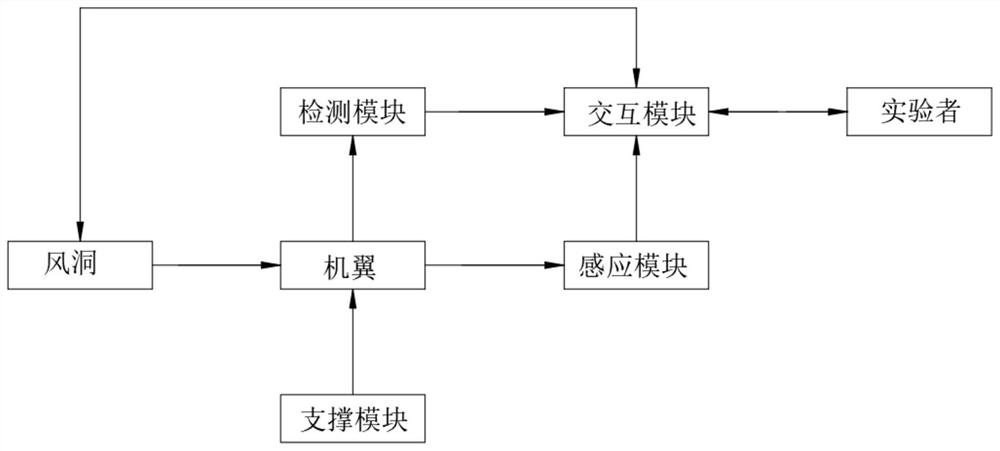
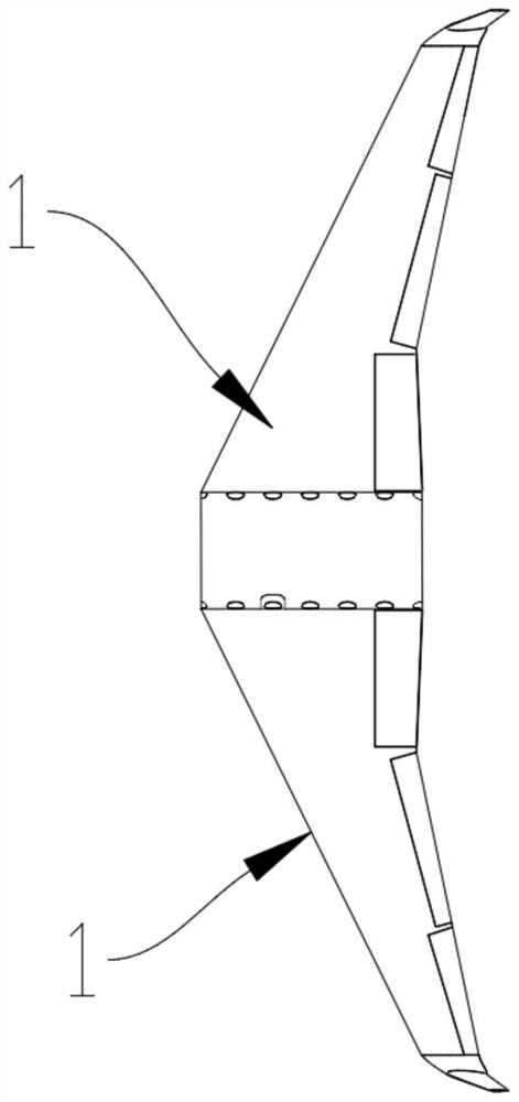
[0053] according to figure 1 , figure 2 , image 3 , Figure 4 , Figure 5 , Image 6 , Figure 7 As shown, this embodiment provides a detection system applied to an active drag reduction experiment of aerospace fluids, including a wind tunnel, a wing, a detection module, and an induction module,

[0054] The detection module is used to detect the fluid on both sides of the wing to detect fluid velocity data on both sides of the wing;

[0055] The sensing module is used for sensing the deformation of the airfoil to analyze the drag reduction capability of the airfoil;

[0056] The detection module and the sensing module are arranged on the wing to detect the amplitude and fluid data of the wing;

[0057] The detection module includes a detection unit and a sampling unit, the detection unit is used to detect the fluid velocity on both sides of the airfoil; the sampling unit is used to detect the transformation amplitude of the airfoil;

[0058] The detection system fur...

Embodiment 2

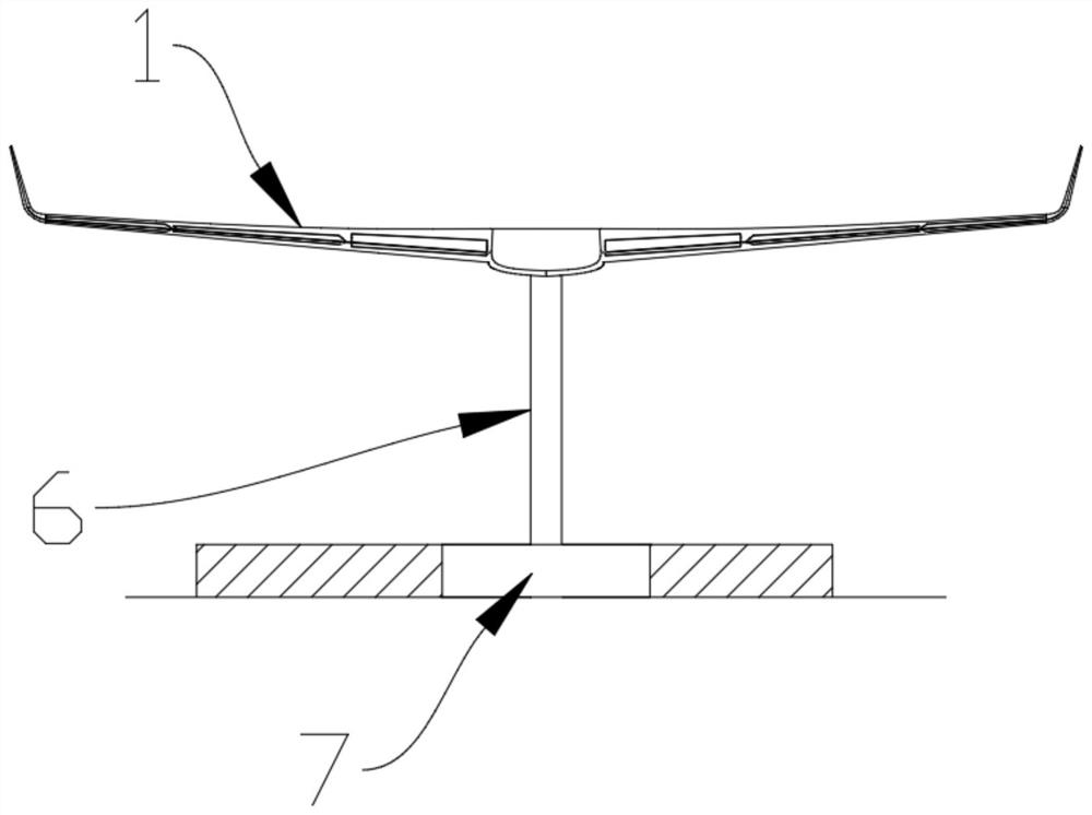
[0113] This embodiment should be understood as including at least all the features of any one of the foregoing embodiments, and further improved on the basis thereof, according to figure 1 , figure 2 , image 3 , Figure 4 , Figure 5 , Image 6 , Figure 7 As shown, the support detection unit also includes a strain gauge sensor, a microprocessor and a feedback device, and the feedback device is used to feed back the processing result of the microprocessor to the interaction module; the microprocessors respectively control connection with the strain gauge sensor and feedback device;

[0114] The strain sensor is arranged on the rod body of the support rod, wherein the lateral strain force and the longitudinal strain of the support rod are detected;

[0115] The microprocessor obtains the rising strain k of the wing lift force to the support rod in one cycle, and the strain index G(k) generated by the support rod is calculated according to the following formula:

[0116...


PUM


Abstract

The invention provides a detection system applied to an aerospace fluid active drag reduction experiment, which comprises a wind tunnel, a wing, a detection module and an induction module, and is characterized in that the detection module is used for detecting fluid at two sides of the wing so as to detect fluid speed data at two sides of the wing; the sensing module is used for sensing the deformation quantity of the wing so as to analyze the resistance reduction capability of the wing; the detection module and the sensing module are arranged on a wing to detect the amplitude and fluid data of the wing; the detection unit comprises a detection component and a resistance reduction component, and the detection probe is used for detecting the fluid speed on the two sides of the wing; and the resistance reduction component is used for adjusting the resistance of the wing so as to cooperatively detect the fluid speed before and after resistance reduction. The resistance of the resistance reduction component is adjusted according to the detection data of the detection unit, so that the change of the wing under the active resistance reduction condition is obtained, the resistance reduction means of the wing can be adjusted by civil aviation, and the resistance reduction efficiency of the wing is improved.

Description

technical field [0001] The invention relates to the technical field of aerospace, in particular to a detection system applied to an aerospace fluid active drag reduction experiment. Background technique [0002] Drag reduction is the eternal theme of aircraft design. In recent years, drag reduction technology has developed rapidly, and there are various methods of drag reduction. different. For example, the drag reduction effect of the pit is better at the low speed stage, while the drag reduction effect of the bulge at the transonic stage is more obvious, but it will increase the drag at low speed conditions. These drag reduction methods are passive, set in advance and cannot be changed. There is no feedback and automatic control cannot be realized. [0003] After searching the prior art, it is found that the prior art CN102595758A discloses a dielectric barrier discharge plasma trailing edge jet device and method, which relates to flow control technology. It is used to ...

Claims


Application Information

Patent Timeline
Patent Type & Authority Applications(China)
IPC IPC(8): G01M9/02G01M9/04G01M9/06G01H9/00G01H11/08G01L9/08G01L11/02G01P5/12
CPCG01M9/02G01M9/04G01M9/06G01H9/00G01H11/08G01P5/12G01L9/08G01L11/02Y02T90/00
Inventor 屠毅陈宣任尹亮郑秋云曾宇姜茜
Owner HUNAN UNIV OF ARTS & SCI
Why Eureka
Try Eureka