Pneumatically controlled high-low energy switching device

A switching device, pneumatic control technology, applied in electrical components, climate sustainability, final product manufacturing, etc., can solve problems such as insufficient insulation distance, small contact head spacing, structural space impact, etc., to achieve convenient assembly and maintenance, Good contact, low cost effect

Pending Publication Date: 2022-07-08
BEIJING SHUOKE ZHONGKEXIN ELECTRONICS EQUIP CO LTD
View PDF0 Cites 0 Cited by
  • Summary
  • Abstract
  • Description
  • Claims
  • Application Information

AI Technical Summary

Problems solved by technology

[0003] In addition, due to the influence of structural space, the commonly used switches are not suitable for normal switching of tens to hundreds of kilovolts of high voltage and do not meet the insulation distance requirements.

Method used


Image

  • Pneumatically controlled high-low energy switching device
  • Pneumatically controlled high-low energy switching device
  • Pneumatically controlled high-low energy switching device

Examples


Embodiment Construction

[0020] The present invention will be described in detail below with reference to the accompanying drawings and in conjunction with the embodiments. It should be noted that the embodiments of the present invention and the features of the embodiments may be combined with each other under the condition of no conflict. For the convenience of description, the words "up", "down", "left" and "right" appear in the following text, which only means that the directions of up, down, left and right are consistent with the drawings themselves, and do not limit the structure.

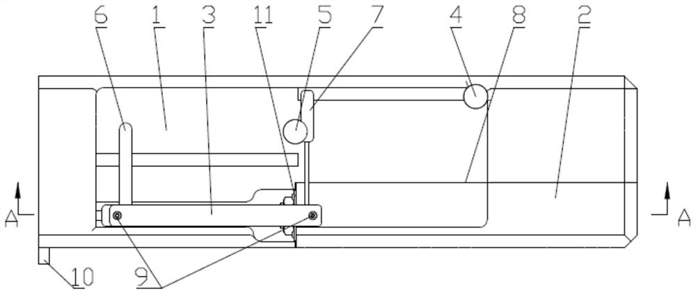
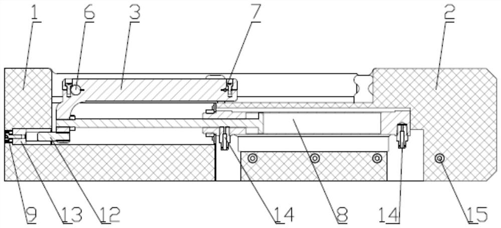
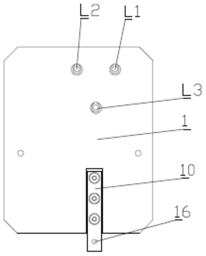
[0021] like figure 1 , figure 2 As shown, a seated pneumatically controlled high-low energy switching device provided in this embodiment includes a mounting seat 1, a fixing seat 2, a connecting rod 3, a first conductive column 4, a second conductive column 5, and a first copper rod 6. The second copper rod 7 , the telescopic drive member 8 , the screw 9 , the ground wire connection block 10 , the pressure plate 11...


PUM


Abstract

The invention provides a high-low energy switching device under pneumatic control. The switching device comprises a mounting base, a fixing base, a connecting rod, a first conductive column, a second conductive column, a first copper rod, a second copper rod, a telescopic driving piece, a male head and a female head. The connecting rod is connected with a telescopic rod of the telescopic driving piece, and the first copper rod and the second copper rod are arranged at the two ends of the connecting rod respectively; the first copper rod is arranged close to the tail end of the telescopic rod; the second conductive column and the first conductive column are arranged in the mounting seat at an interval; the male head is arranged at the tail end of the connecting rod, and the female head corresponding to the male head in position is arranged on the mounting seat; one end of the female head away from the male head is grounded; the first conductive column is connected with a first high-voltage cable and a second high-voltage cable, and the second conductive column is connected with a high-voltage cable. Compared with the prior art, switching among different energies is realized by changing the wiring mode under the condition that the electrical clearance is met.

Description

technical field [0001] The invention relates to the technical field of semiconductor device manufacturing, in particular to a high-low energy switching device controlled by pneumatics. Background technique [0002] Ion implantation doping is an essential key process in semiconductor manufacturing technology. Depending on the implanted elements, the required ionization energy gap is huge. Ion implantation is divided into low energy and high energy. Switching different implantation energy can expand the application range of ion implantation, which can be applied to the fields of semiconductor device manufacturing and modification of different materials. It is necessary to ensure the injection quality and also need to be completed with high efficiency. Due to the need to switch the implantation energy, safety factors must be considered. In the ion implantation process, a voltage of tens to hundreds of kilovolts is usually added. [0003] In addition, the commonly used switche...

Claims


Application Information

Patent Timeline
IPC IPC(8): H01J37/248H01J37/317
CPCH01J37/3171H01J37/248Y02P70/50
Inventor 何珍光李士会张冰郭森季杰
Owner BEIJING SHUOKE ZHONGKEXIN ELECTRONICS EQUIP CO LTD
Why Eureka
Try Eureka