
Partial bootstrap gate drive circuit capable of reducing switching loss and control method

A gate drive and switching loss technology, which is applied in some bootstrap gate drive circuits and control fields, can solve problems such as damage to device reliability, gate overcharge, and increase cost, so as to overcome the limitation of switching speed and improve switching. Speed, the effect of reducing switching loss

Pending Publication Date: 2022-07-08
深圳市优联半导体有限公司 +1
View PDF0 Cites 0 Cited by
  • Summary
  • Abstract
  • Description
  • Claims
  • Application Information

AI Technical Summary

Problems solved by technology

However, on the one hand, the additional power supply greatly increases the cost of the driver. On the other hand, due to the stability of the gate oxide of the switching device, the voltage increase space used by the driver is very small.
[0008] (2) The drive circuit based on the current source needs to use an additional inductance to generate a constant current. On the one hand, the additional inductance increases the cost, and on the other hand, an additional control circuit is required
More importantly, if the charging time is not well controlled during the process of charging the gate with an inductor, it will lead to overcharging of the gate, and due to the stability of the gate oxide of the switching device, the excessively high gate Extreme voltage will damage the reliability of the device, and in serious cases will directly damage the device
[0009] (3) The existing active driving circuit with complex control logic needs to switch the output voltage or output current in real time according to the working state of the switching device. Although this method can provide the best driving performance in theory, its normal operation is extremely dependent on the Monitoring of working status of switching devices
On the one hand, additional monitoring hardware will increase the cost, on the other hand, the measured information needs to be calculated in the microcontroller, which will lead to the occupation of computing resources
[0010] (4) The traditional drive circuit only needs one control signal, while the existing current source drive circuit or active drive circuit often needs a large number of auxiliary control signals to ensure the normal operation of the circuit
Too many control signals will not only occupy more microcontroller port resources, but also make the anti-interference ability of the drive circuit worse

Method used


Image

  • Partial bootstrap gate drive circuit capable of reducing switching loss and control method
  • Partial bootstrap gate drive circuit capable of reducing switching loss and control method
  • Partial bootstrap gate drive circuit capable of reducing switching loss and control method

Examples


Embodiment Construction

[0056] In order to make the objectives, technical solutions and advantages of the present invention clearer, the present invention will be further described in detail below with reference to the embodiments. It should be understood that the specific embodiments described herein are only used to explain the present invention, but not to limit the present invention.

[0057] In view of the problems existing in the prior art, the present invention provides a partial bootstrap gate driving circuit and a control method for reducing switching loss. The present invention is described in detail below with reference to the accompanying drawings.

[0058] 1. Explain the embodiment. In order for those skilled in the art to fully understand how the present invention is specifically implemented, this part is an explanatory embodiment for expanding the description of the technical solutions of the claims.

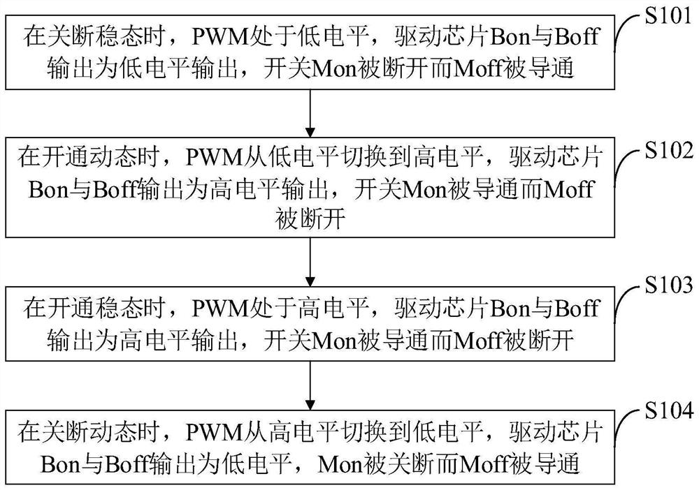
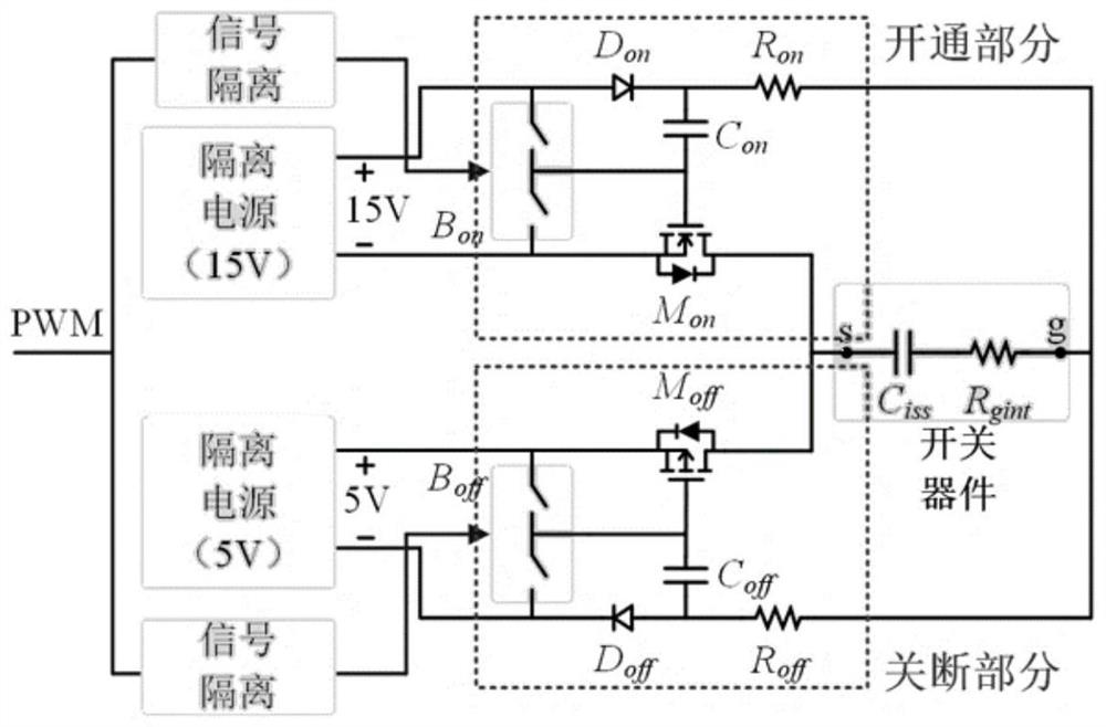
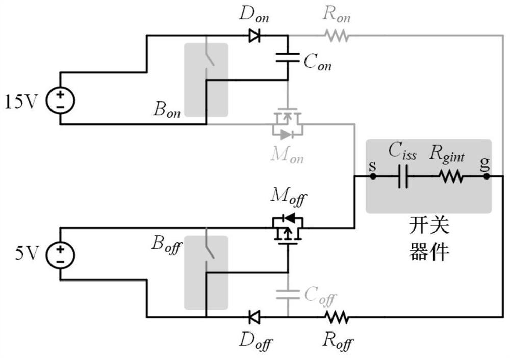
[0059] like figure 1 As shown, the control method for a partial bootstrap gate dr...


PUM


Abstract

The invention belongs to the technical field of gate drive circuits, and discloses a partial bootstrap gate drive circuit capable of reducing switching loss and a control method, and the partial bootstrap gate drive circuit capable of reducing switching loss comprises a switching device, a PWM, a power supply, a signal isolator, a non-isolated drive chip, a bootstrap structure, a drive resistor, a Mon and a Moff. Compared with voltage source type driving, the switching speed can be obviously improved, and the switching loss can be reduced; compared with current source type driving, the method has the characteristic of self-adaption, additional time sequence control is not needed, and the risk of switching device loss caused by overcharge does not exist; compared with complex active driving, the method has the advantages of being simple in result and high in reliability. A bootstrap structure is used, voltage-multiplying output can be achieved on the premise that a power supply is not added, the limitation that a wide bandgap device is larger in parasitic resistance in a gate pole is overcome, and switching loss can be remarkably reduced.

Description

technical field [0001] The invention belongs to the technical field of gate drive circuits, and in particular relates to a partial bootstrap gate drive circuit and a control method for reducing switching loss. Background technique [0002] At present, with the development of transportation electrification and new energy, more and more power electronic converters have been applied. Efficiency improvement of power electronic converters plays a crucial role in reducing energy consumption and carbon emissions, and reducing switching losses is one of the main ways to improve converter efficiency. The switching loss of the converter is directly related to the gate drive circuit used. By improving the gate drive circuit to reduce the switching loss, energy can be saved and carbon emissions can be reduced. Therefore, it is of great significance to develop gate drive techniques that can reduce switching losses. [0003] At present, the gate drive circuits at home and abroad mainly ...

Claims


Application Information

Patent Timeline
Patent Type & Authority Applications(China)
IPC IPC(8): H02M1/08
CPCH02M1/08Y02B70/10H02M1/0054H02M1/0029H02M1/088
Inventor 王智强钱承辛国庆时晓洁
Owner 深圳市优联半导体有限公司
Learn More