Aircraft component frame beam gap design method, device and equipment and storage medium

A technology of aircraft components and design methods, applied in computer-aided design, design optimization/simulation, calculation, etc., can solve problems such as low efficiency of design methods, achieve the effects of omitting repetitive work, meeting product quality requirements, and improving test efficiency

Pending Publication Date: 2022-07-12
CHENGDU AIRCRAFT INDUSTRY GROUP
View PDF0 Cites 1 Cited by
  • Summary
  • Abstract
  • Description
  • Claims
  • Application Information

AI Technical Summary

Problems solved by technology

[0004] Aiming at the defect of low efficiency of the design method existing in the prior art, the present invention discloses a design method, device, equipment and storage medium for frame and girder gaps of aircraft components. The method of the present invent

Method used


Image

  • Aircraft component frame beam gap design method, device and equipment and storage medium
  • Aircraft component frame beam gap design method, device and equipment and storage medium
  • Aircraft component frame beam gap design method, device and equipment and storage medium

Examples


Embodiment approach 1

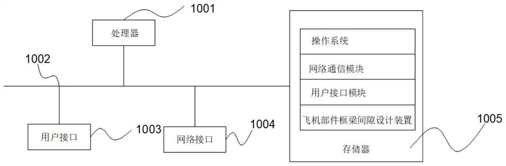
[0052] This embodiment, as a basic embodiment of the present invention, refers to figure 1 , figure 1 This is a schematic structural diagram of an electronic device of the hardware operating environment involved in the solution of the embodiment of the present application.

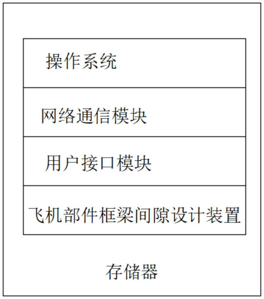
[0053] like figure 1 As shown, the production equipment may include: a processor 1001 , such as a central processing unit (Central Processing Unit, CPU), a communication bus 1002 , a user interface 1003 , a network interface 1004 , and a memory 1005 . Among them, the communication bus 1002 is used to realize the connection and communication between these components. The user interface 1003 may include a display screen (Display), an input unit such as a keyboard (Keyboard), and the optional user interface 1003 may also include a standard wired interface and a wireless interface. Optionally, the network interface 1004 may include a standard wired interface and a wireless interface (eg, a wireless fidelity...

Embodiment approach 2

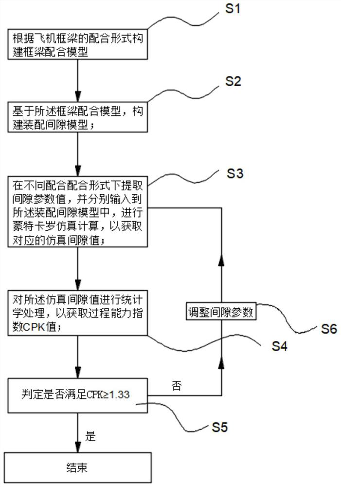
[0101] This embodiment, as a basic embodiment of the present invention, discloses a method for designing a frame beam gap of an aircraft component. In this embodiment, a front and a rear frame are connected by a positioning beam for cooperation. In the above matching relationship, The end faces on both sides of the beam and the frame web are positioned through the positioning holes, and a gap is formed between the beam end and the frame web. In this embodiment, the structural assembly gap compensation threshold is 0.2mm, that is, USL=0.2, LSL=0;

[0102] S1. Build a frame-beam fitting model according to the fitting form of the aircraft frame-beam;

[0103] Draw the structure diagram of the frame and beam according to the actual structure of the frame beam, and draw the assembly diagram of the frame and the beam according to the actual assembly relationship. The assembly diagram is the frame-beam matching model. , the frame-beam fitting model is as follows Figure 5 shown;

...


PUM


Abstract

The invention discloses an aircraft component frame beam gap design method, device and equipment and a storage medium, a corresponding assembly gap model is established by extracting a gap parameter value of a frame beam matching model, a corresponding simulation gap value is calculated through a Monte Carlo simulation algorithm, and finally a CPK value is calculated through the simulation gap value. The corresponding gap parameter value is adjusted according to the CPK value to ensure that the gap parameter value of the final design scheme meets the design requirement; according to the invention, Montero simulation calculation is used for replacing a real object verification test, so that the test cost is reduced, and the test efficiency is improved; meanwhile, the CPK value is introduced and serves as the basis for adjusting the gap parameter value, so that the influence of the technological process capacity on the gap value is considered during gap design, the simulation value is calculated based on the influence, the gap is correspondingly adjusted, the adjusting process is more targeted and instructive, and the efficiency and precision of gap design adjustment are improved; and meanwhile, the final optimization result better meets the product quality requirement, and is more real and reliable.

Description

technical field [0001] The present invention relates to the technical field of aircraft component design, in particular to a frame beam gap design method, device, equipment and storage medium for aircraft components. Background technique [0002] In modern aircraft manufacturing and assembly, due to the influence of parts manufacturing error, assembly positioning error and other factors, there will be a certain gap between the structures. The existence of the structural gap will affect the strength of the structural assembly. Under the superposition of aircraft load and stress, the fatigue life of the aircraft structure will be affected. adversely affect. The assembly gap can be eliminated by adding fillers. Generally, according to the measurement results of the gap value, the equivalent gaskets or fillers with different thickness specifications are selected to compensate; but in actual engineering, the gaskets cannot completely correspond to the structural gaps. Therefore,...

Claims


Application Information

Patent Timeline
IPC IPC(8): G06F30/15G06F30/17G06F30/20G06F111/08G06F113/28G06F119/02G06F119/14
CPCG06F30/15G06F30/17G06F30/20G06F2111/08G06F2113/28G06F2119/14G06F2119/02Y02T90/00
Inventor 杨建成勾江洋陈雪梅何鹏益建朋陈清良刘元吉叶翔宇
Owner CHENGDU AIRCRAFT INDUSTRY GROUP
Why Eureka
Try Eureka