Preparation device of pathogenic microorganism transfer liquid and preparation method of transfer liquid

A pathogenic microorganism and preparation device technology, which is applied to the field of pathogenic microorganism transport liquid preparation device and transport liquid preparation, can solve the problems that the transport liquid is difficult to preserve pathogens, cannot be used for transport at the same time, and is inconvenient to detect pathogenic microorganisms, etc., and achieves preservation of RNA and DNA. Integrity, convenient nucleic acid detection, and the effect of reducing the risk of infection

Pending Publication Date: 2022-07-15
大能生物科技(南京)有限公司
8 Cites 0 Cited by

AI-Extracted Technical Summary

Problems solved by technology

[0004] The purpose of the present invention is to solve the pathogenic microorganism transport liquid in the prior art, which cannot be applied to the transfer of bacterial samples and virus samples at the same time, and the transfer liquid is difficult to preserve the activity of pathogens, which is not convenient for subsequent detection of pathogenic microorganisms. , and a p...

Method used

As shown in Figure 6 and Figure 9, described mixing tank 50 is provided with three, arranges successively respectively, and three described guide tubes 47 stretch in the mixing tank 50, and the bottom of described guide tube 47 is positioned at Between the middle and the top of the stirring tank 50, a third electromagnetic valve 51 is respectively arranged between the output end drawn from the lower end of the stirring tank 50 and the second three branch pipes 48, and the stirring tank 50 includes a tank Body 52, base 53 and stirring rod 54, the base 53 is fixed on the bottom backing plate 15, the tank body 52 is a cylindrical cavity structur...

Abstract

The pathogenic microorganism transfer liquid preparation device comprises an equipment compartment, a liquid mixing mechanism, a filling mechanism and a control terminal, the liquid mixing mechanism is located at one end in the equipment compartment, and the liquid mixing mechanism comprises a first storage box, a second storage box, a third conveying pump and a stirring tank; the filling mechanism is located at the other end in the equipment compartment and comprises a lower conveying belt, an upper conveying belt and a lifting mechanism. The preparation method of the transfer liquid comprises the steps of medicament mixing and medicament filling. The pathogenic microorganism transfer liquid preparation device disclosed by the invention realizes automatic filling of the transfer liquid, is light and convenient to move, meets the detection requirements of sudden and large-scale pathogenic microorganisms in local areas, and is suitable for transferring bacterial samples and RNA virus samples or DNA virus samples after sampling; the non-inactivated transfer liquid can maintain the activity of pathogens to the maximum extent, and can be used for pathogen detection and pathogen culture and separation subsequently.

Application Domain

Filling using suctionMixer accessories +1

Technology Topic

PathogenPathogenic microorganism +6

Image

  • Preparation device of pathogenic microorganism transfer liquid and preparation method of transfer liquid
  • Preparation device of pathogenic microorganism transfer liquid and preparation method of transfer liquid
  • Preparation device of pathogenic microorganism transfer liquid and preparation method of transfer liquid

Examples

  • Experimental program(4)

Example Embodiment

[0037] Example 1:
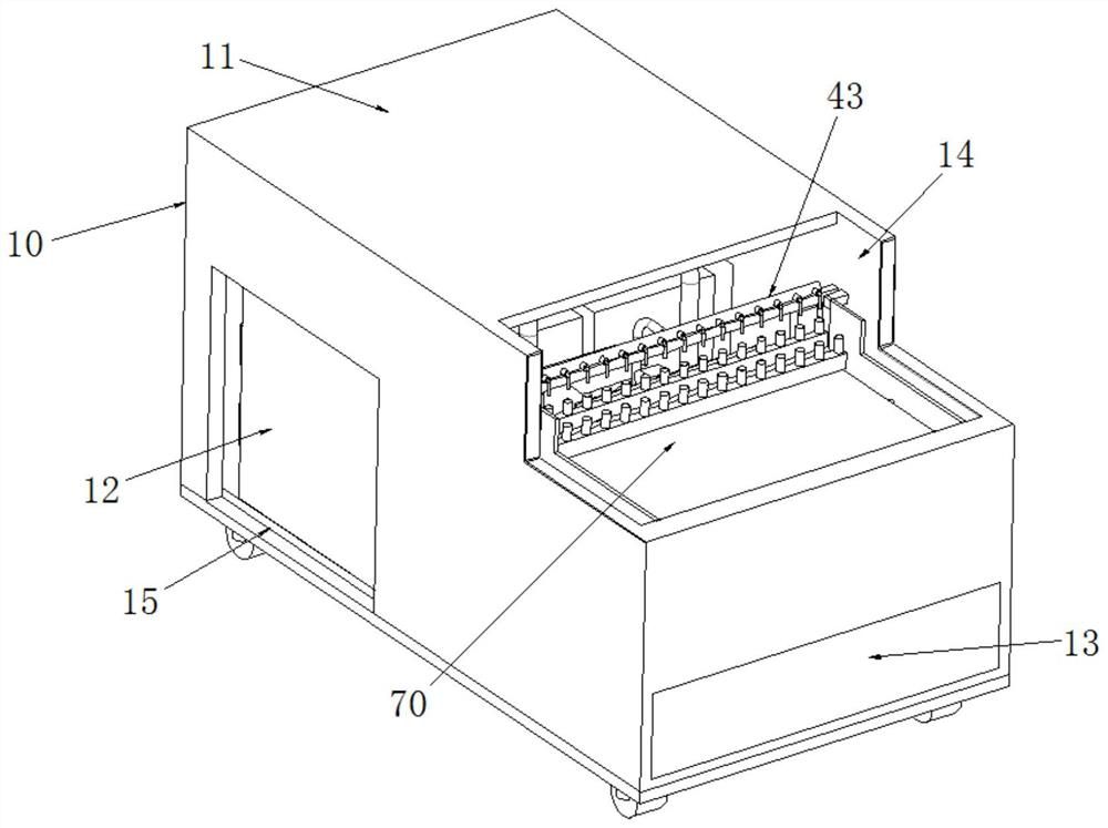
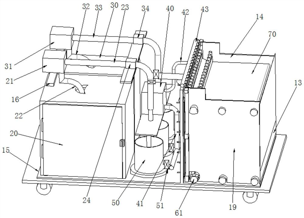
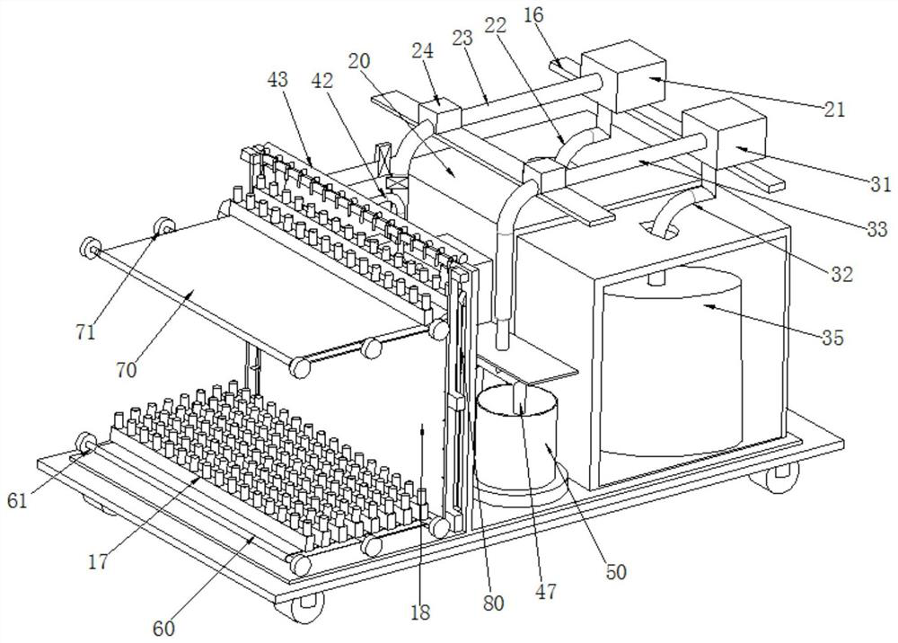
[0038] refer to Figure 1-3 , a pathogenic microorganism transport liquid preparation device, including an equipment compartment 10, a liquid mixing mechanism, a filling mechanism and a control terminal. The lower four corners of the plate 15 are provided with universal wheels, the top of one side of the nozzle 43 is provided with a placement table 11, and the other side is provided with a collection port 14, and the equipment compartment 10 is connected to the first. The two sides corresponding to the storage box 20 and the second storage box 30 are provided with liquid storage ports 12, and the side corresponding to the lower conveyor belt 60 is provided with a conveying port 13, and the lower port of the conveying port 13 is lower than the On the upper surface of the lower conveyor belt 60, its upper end surface is not higher than the lower surface of the upper conveyor belt 70, the upper surface of the upper conveyor belt 70 is located in the collection port 14, and the two sides of the collection port 14 are respectively A limiting baffle 19 is provided to limit the movement of the filling tray 17 , the lower end of the limiting baffle 19 is carried on the bottom plate 15 , the first delivery pump 21 , the second delivery pump 31 , The first flowmeter 24 , the second flowmeter 34 and the third delivery pump 40 are respectively fixed on the support plate 16 , the support plate 16 is a strip-shaped plate structure, and the two ends of the support plate 16 are respectively fixed on the sides of the equipment compartment 10 . Both sides of the inner wall of the box.
[0039] like image 3 , Figure 4 and Image 6 As shown, the liquid mixing mechanism is located at one end of the equipment compartment 10, which includes a first storage tank 20, a second storage tank 30, a third delivery pump 40 and a stirring tank 50, and the filling mechanism is located in the At the other end of the equipment compartment 10, the filling mechanism includes a lower conveyor belt 60, an upper conveyor belt 70 and a lifting mechanism 80. The first storage box 20 stores a first solution tank 25, and the first solution tank 25 passes through the first solution tank 25. A suction pipe 22 is connected to the input end of the first delivery pump 21 , the output end of the first delivery pump 21 is connected to the first delivery pipe 23 , and a second solution tank 35 is placed in the second storage tank 30 . The solution tank 35 is connected to the input end of the second delivery pump 31 through the second suction pipe 32, the output end of the second delivery pump 31 is connected to the second delivery pipe 33, and the first storage tank 20 and the second storage tank 30 are controllable. The temperature box is provided with a heating wire inside the box body plate, and a temperature sensor is arranged in the box, and the temperature sensor is connected with the control terminal; The one or three branch pipes 46 are divided into three guide pipes 47 and are respectively connected to the stirring tank 50. The lower ends of the stirring tank 50 are respectively led out and connected to the second three branch pipes 48. The second three branch pipes 48 pass through the third branch pipe 48. The suction pipe 41 is connected with the third delivery pump 40 , the output end of the third delivery pump 40 is connected with a third delivery pipe 42 , and the third delivery pipe 42 is connected with a spray pipe 43 , which is evenly distributed on the spray pipe 43 . A plurality of nozzles 44, a straight pipe 26 is provided on the pipe between the first flow meter 24 and the first three branch pipes 46 on the first conveying pipe 23, and the straight pipe 26 communicates with the nozzle pipe 43 and the first three branch pipes 46. For the first conveying pipe 23, a first solenoid valve 27 is provided on the straight pipe 26, a second solenoid valve 28 is provided between the straight pipe 26 and the first three branch pipes 46, and a screw is provided on the nozzle 44. Switch 45 , the nozzle 44 corresponds to the solution bottle on the filling tray 17 .
[0040] like Figure 5 , Figure 7 and Figure 8 As shown, the lower side of the nozzle 44 is respectively provided with an upper conveyor belt 70 and a lower conveyor belt 60, the lower conveyor belt 60 and the upper conveyor belt 70 are used for conveying the filling tray 17, and the same side of the two are provided with Lifting mechanism 80, the lifting mechanism 80 includes a frame 81 and a motor 82, the frame 81 is a "傂"-shaped structure, and the baffle 18 is embedded in the frame, and the nozzle 43 is arranged at the top of the frame 81, so Motors 82 are respectively provided on both sides of the upper part of the frame 81 , a belt 83 is provided at the output end of the motor 82 , and several lifting plates 84 are uniformly fixed on the belt 83 .
[0041] The filling holder 17 has a cuboid structure, and the upper half of the filling holder 17 is evenly provided with a accommodating cavity along the axis direction. A solution bottle is inserted in the accommodating cavity. The number of the accommodating chambers is not less than the number of the nozzles 44, and the length of the filling tray 17 is less than the width of the lower conveyor belt 60, and the length of the filling tray 17 is the same as the length of the lifting plates 84 on both sides. The lengths between the outer sides are the same, the lower conveyor belt 60 is provided with a number of not less than three lower transmission rods 61, and the upper conveyor belt 70 is provided with a number of not less than three upper transmission rods 71 , both ends of the lower transmission rod 61 and the upper transmission rod 71 are fixed on the limiting plate 19, and the lower conveyor belt 60 and the upper conveyor belt 70 are provided with lower guide slides on one side of the lower conveyor belt 60 and the upper conveyor belt 70 close to the lifting mechanism 80, respectively. Block 62 and upper guide block 72, the lower guide block 62 and the upper guide block 72 are located between the lifting plate 84, and the angle between the lifting plate 84 and the belt 83 ranges from eighty to eighty Between five degrees, the cross-sections of the lower guide block 62 and the upper guide block 72 are both right-angled triangle structures, and the right-angled side of the lower guide block 62 is close to the side of the lower conveyor belt 60. The right-angled side of the upper guide block 72 is close to the side of the partition plate 18 . The top of the partition plate 18 is provided with a hollow portion, and the lower surface of the hollow portion is provided with a push plate 92 , and the push plate 92 is a plate One side corresponds to the filling tray 17, and the middle part of the other side is connected with the output conducting rod 91 of the servo electric cylinder 90, and the servo electric cylinder 90 is fixed to the partition plate through the bearing tray 93 18 on.
[0042] like Image 6 and Figure 9 As shown in the figure, three stirring tanks 50 are provided, which are arranged in sequence, and the three guiding pipes 47 extend into the stirring tank 50, and the bottoms of the guiding pipes 47 are located from the middle to the top of the stirring tank 50. A third solenoid valve 51 is respectively provided between the output end drawn from the lower end of the stirring tank 50 and the second three branch pipes 48 , and the stirring tank 50 includes a tank body 52 , a base 53 and a stirring rod 54 , the base 53 is fixed on the bottom plate 15, the tank 52 is a cylindrical cavity structure, and is fixed on the upper surface of the base 53, its top is open or closed, and the inner bottom is provided There is a stirring rod 54, and the stirring tank 50 utilizes the characteristics of magnetic substances that are of the same nature and repelling each other, and pushes the stirring rod 54 to rotate by constantly changing the polarities at both ends of the base 53, and drives the liquid in the tank 52 to rotate through the rotation of the stirring rod 54, so that the liquid is uniform. During mixing, when the stirring rod 54 rotates, the base 53 can perform a heating function to heat the mixed liquid in the tank body 52 to increase the liquid mixing speed.
[0043] The pathogenic microorganism transport liquid preparation device, by separately installing the first transport pump 21, the second transport pump 31, the third transport pump 40 and the connecting pipeline, can transfer the non-inactivated transport liquid in the first solution tank 25 through the first transport The pump 21 and the third delivery pump 40 are directly filled into the solution bottle of the filling holder 17; when the inactivated transport fluid needs to be used, the first delivery pump 21, the second delivery pump 31 and the third delivery pump 40 cooperate with each other. , the non-inactivated transport liquid and the guanidine salt inactivator are stirred and mixed evenly in the stirring tank 50 to form an inactivated transport liquid for use. The filling and preparation device is light and easy to move, not limited by space and region, and meets the needs of sudden and large-scale detection of pathogenic microorganisms in local areas.

Example Embodiment

[0044] Embodiment 2:
[0045] In this embodiment, the method for preparing the transport liquid is carried out by using the pathogenic microorganism transport liquid preparation device in the first embodiment, and the preparation method includes the following steps:
[0046] Step 1: First, inject the non-inactivated transport liquid into the first solution tank 25, inject the guanidine salt inactivator into the second solution tank 35, store it, and pass the filling tray 17 through the delivery port 13 on the equipment compartment 10 in turn. It is placed on the lower conveyor belt 60, and the first delivery pump 21 and the second delivery pump 31 are activated through the control terminal to inject the non-inactivated transport fluid in the first solution tank 25 and the guanidine salt inactivator in the second solution tank 35. In the stirring tank 50, the first flow meter 24 and the second flow meter 34 are used to monitor the liquid delivery volume in the first delivery pipe 23 and the second delivery pipe 33 in real time during liquid delivery, and the first solenoid valve 27 is closed at this time. state, the second solenoid valve 28 is in the open state;
[0047] Step 2. After the liquid in the first conveying pipe 23 and the second conveying pipe 33 reaches the stirring tank 50, start the stirring tank 50 to drive the stirring rod 54 inside to rotate, and inactivate the injected non-inactivated transport fluid and guanidine salt. The mixed liquid of the agent is stirred to fully mix the liquids, and the mixed liquid is the inactivation transport liquid;
[0048] Step 3: After the non-inactivated transport liquid and the guanidine salt inactivator in step 2 are mixed to obtain the inactivated transport liquid, the lower conveyor belt 60, the upper conveyor belt 70 and the lifting mechanism 80 are started, and the filling tray 17 passes through the lifting mechanism 80 from the lifting mechanism 80. The lower conveyor belt 60 is transferred to the top of the lifting mechanism 80, then the third transfer pump 40 is started, and then the third solenoid valve 51 is opened one by one, and the inactivated transport liquid in the stirring tank 50 is sequentially passed through the third suction pipe 41, the third conveyance The pipe 42 and the nozzle 43, the nozzles 44 evenly distributed on the nozzle 43 inject the inactivated transport liquid into the solution bottle in the filling tray 17 to complete the filling work;
[0049] Step 4. Finally, push the push plate 92 through the output end of the servo electric cylinder 90 to push out the filling tray 17 after filling. The belt 70 is conveyed to the collection port 14 on one side of the equipment compartment 10 for collection.
[0050]Pathogenic microorganism transport fluids, including inactivated transport fluids and non-inactivated transport fluids, the above non-inactivated transport fluids include phosphate buffers, RNase inhibitors, DNase inhibitors, disodium EDTA, biological preservatives, surfactants and trehalose or glycerol, the guanidine salt inactivating agent contains guanidine isothiocyanate; the surfactant is a non-ionic surfactant, and the biological preservative is Proclin 300, by mixing the non-inactivating transport fluid with The guanidine salt inactivator is fully mixed and reacted to obtain an inactivated transport liquid, which can directly lyse the pathogen to release nucleic acid, which is convenient for subsequent nucleic acid detection.

Example Embodiment

[0051] Embodiment three:
[0052] In this embodiment, when using the pathogenic microorganism transport liquid preparation device to prepare the transport liquid, the second transport pump 31 and the second solenoid valve 28 are closed, the first transport pump 21 and the first solenoid valve 27 are opened, and the first solution The non-inactivated transport liquid in the tank 25 is injected into the solution bottle in the filling tray 17 through the nozzle 44, and the non-inactivated transport liquid can be directly filled and used. It can be used for the detection of pathogens, as well as for the cultivation and separation of pathogens. The non-inactivated transporter of pathogenic microorganisms can inhibit the activity of RNase and DNase, preserve the integrity of RNA and DNA, and realize the storage and transportation of samples at room temperature, among which the inactivation transport The solution can rapidly inactivate pathogens at room temperature, reducing the risk of infection for operators and reducing false negatives in the test.

PUM

no PUM

Description & Claims & Application Information

We can also present the details of the Description, Claims and Application information to help users get a comprehensive understanding of the technical details of the patent, such as background art, summary of invention, brief description of drawings, description of embodiments, and other original content. On the other hand, users can also determine the specific scope of protection of the technology through the list of claims; as well as understand the changes in the life cycle of the technology with the presentation of the patent timeline. Login to view more.

Similar technology patents

Dry-type transformer

InactiveCN106504857Aeasy to moveEasy to install
Owner:JIANGSU YAWEI TRANSFORMER

Bean sprout washing equipment

InactiveCN108741139Aeasy to moveavoid jamming
Owner:WUXI SUYA FOOD CO LTD

Medical equipment transferring storage box having moisture-proof function

InactiveCN108466755Agood moisture resistanceeasy to move
Owner:ZHENGZHOU RENHONG PHARMA CO LTD

Display model for garment and leather product design

Owner:SHAANXI INST OF INT TRADE & COMMERCE

Solar energy vehicle building

InactiveCN101451398Aeasy to movecomfortable to use
Owner:SHANGHAI QIYI HIGH SCHOOL

Classification and recommendation of technical efficacy words

  • easy to move

Backpack medlar-picking machine

InactiveCN101473731Aeasy to movenovel structure
Owner:CHINA AGRI UNIV

Stream media broadcasting method and system

InactiveCN103763637AEasy to transfereasy to move
Owner:CHINA NSTV

Water drainage and gas production simulated experimental device

InactiveCN101806202Aeasy to move
Owner:CHINA UNIV OF PETROLEUM (EAST CHINA)

Hydraulic self-moving steel mould trolley and construction method thereof

ActiveCN103437782AFlexible removal locationeasy to move
Owner:CHINA THREE GORGES CORPORATION +1

Conference show device

InactiveCN107856443Aeasy to moveEasy and stable placement
Owner:广州小造电子商务有限公司
Why Eureka
Try Eureka