Complex stratum pipe jacking working well and construction technology thereof

A technology of complex strata and construction technology, applied in artificial islands, water conservancy projects, infrastructure projects, etc., can solve the problems of difficult precipitation, low cost, inability to precipitation, etc., and achieve the effect of simple process, improved work efficiency, and obvious water stop effect.

Pending Publication Date: 2022-07-29
西安市政道桥建设集团有限公司
View PDF2 Cites 2 Cited by
  • Summary
  • Abstract
  • Description
  • Claims
  • Application Information

AI Technical Summary

Problems solved by technology

[0006] The purpose of the present invention is to overcome the problems in the prior art and provide a construction process for pipe jacking wells in complex formations. The steel sheet pile support plus grouting and water-stopping process of the present invention, and the external grouting reinforcement of the steel sheet piles, can solve the problem. No precipitation, difficult precipitation and other problems, and the cost is low

Method used


Image

  • Complex stratum pipe jacking working well and construction technology thereof

Examples


Embodiment

[0044] A 330KV power pipeline project crosses the Juhe River along Chang'an Avenue, with a total length of 3380m and a pipe diameter of D2000mm, of which the lower crossing of the Juhe River is 122m long and 12m deep. The geological conditions of this section of the project are: I alluvial fan II alluvial fan, 1-2.5m of miscellaneous fill, 2.5-7m of sand and pebble layer (maximum particle size 250mm), 7-9m of silty clay, 9-12m of sand and pebble Layer (maximum particle size 100mm), 12-16m medium sand with a small amount of pebbles, 16-20m silty clay. There is groundwater 1.5m below the ground, the permeability coefficient of silty clay is 4-6m / d, the permeability coefficient of sand and pebble layer is 120m / d, and there is a beam bridge 10m to the right of the pipeline center line.

[0045] The grouting in the working well is through drilling, and then injecting cement or cement and water glass slurry 0-3m below the bottom of the hole, and the slurry squeezes out the water or ...

Embodiment 2

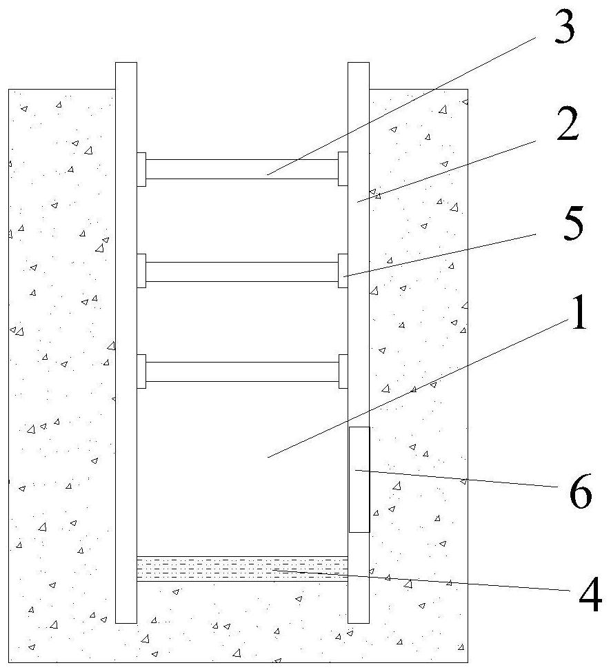
[0055] The structure of the pipe jacking working well is specifically shown in the accompanying drawings, including a working well foundation pit 1, a steel sheet pile 2, a purlin 3, and a reinforced concrete slab 4; the steel sheet pile 2 is vertically fixed on the inner wall of the working well foundation pit 1, The purlin 3 is fixedly connected to the steel sheet pile 2 through the purlin support 5; the reinforced concrete slab 4 is laid at the bottom of the well, and the steel sheet pile 2 has no hole 6 for pipe jacking, and the working well The outer periphery and bottom of the foundation pit 1 are filled with slurry.


PUM


Abstract

The invention discloses a complex stratum pipe-jacking working well and a construction technology thereof, and belongs to the technical field of pipe-jacking working well construction. The complex stratum pipe jacking working well construction technology comprises the following steps that the well position is determined; steel sheet pile construction; grouting reinforcement is conducted, specifically, grouting in the working well is conducted through drilling, and then cement or cement and water glass slurry are injected into the position 0-3 m below the pit bottom in a hole; working well outer grouting is conducted from 1.5 m below the ground to 3 m below the well bottom, and the lower portion of the working well outer grouting is connected with a well inner grouting soil body; after grouting is finished, purlin enclosing, supporting and excavation construction is carried out; after excavation is conducted to the bottom of the working well, reinforcing steel bars are bound at the bottom of the well, a concrete bottom plate is poured, equipment is installed in the working well, and after all the equipment is installed and debugged in place, portal steel sheet piles are cut, and pipelines are jacked. The complex stratum pipe jacking working well construction technology is an economical and safe technical measure for complex stratum construction working well construction, the problems of difficult precipitation and the like are solved, and the working efficiency of working well manufacturing is greatly improved.

Description

technical field [0001] The invention relates to the technical field of pipe jacking working well construction technology, in particular to a pipe jacking working well construction technology in complex strata. Background technique [0002] Common construction methods for pipe jacking wells include: reinforced concrete prefabricated caisson, reinforced concrete reverse method, cast-in-place piles and water-stop curtains and other construction methods. The support of the jacking jack needs huge reaction force support, which is provided by the side wall of the working well and the soil behind the wall, so the quality of the working well is related to the success or failure of the whole project, and the equipment installation, pipeline top There must be no water in the working well during the process. [0003] For the complex stratum where the working well is located, the construction is difficult, the groundwater level is high, and the permeability coefficient is large. If th...

Claims


Application Information

Patent Timeline
Patent Type & Authority Applications(China)
IPC IPC(8): E02D29/12E02D17/04E02D19/18E02D5/04
CPCE02D29/12E02D17/04E02D19/18E02D19/185E02D5/04
Inventor 任瑞田瑞刘刚
Owner 西安市政道桥建设集团有限公司
Why Eureka
Try Eureka