Fuel cell stack device

A technology of fuel cell stacks and fuel cells, which is applied in the direction of fuel cells, circuits, electrical components, etc., can solve the problems of large differences in the working state of single-chip batteries, the service performance and life of the stack, and eliminate the excessive difference in working states , Simple processing and manufacturing, and the effect of eliminating temperature and humidity differences

Pending Publication Date: 2022-07-29
BEIJING SINOHYTEC
View PDF1 Cites 3 Cited by
  • Summary
  • Abstract
  • Description
  • Claims
  • Application Information

AI Technical Summary

Problems solved by technology

[0005] In view of the above analysis, the embodiment of the present invention aims to provide a fuel cell stack device to solve the problem in the prior art that the working state of single-chip batteries in different positions is too different to affect the performance and life of the stack

Method used


Image

  • Fuel cell stack device
  • Fuel cell stack device
  • Fuel cell stack device

Examples


Embodiment 1

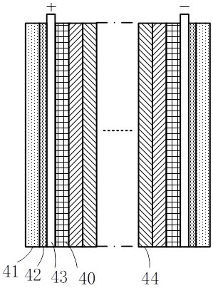
[0055] An embodiment of the present invention discloses a fuel cell stack device, such as Figure 1~2 As shown, it includes a plurality of monolithic cells 44 stacked in one, and dummy cells 40, current collectors 43, insulating plates 42 and end plates 41 which are respectively arranged on the outside of the first cell and the last cell and are stacked in sequence.

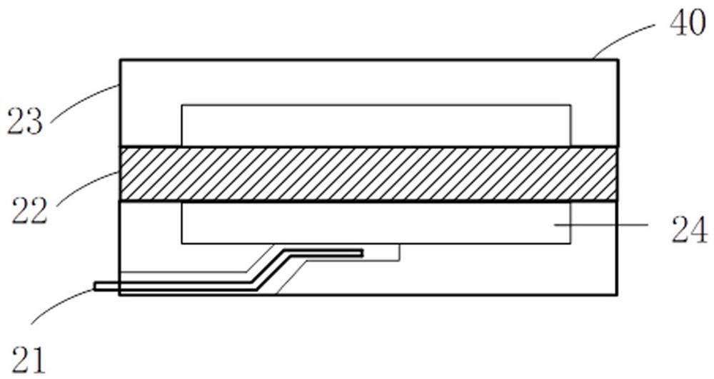
[0056] The dummy battery 40 adopts a sheet-like structure, and further includes a bipolar plate 23, a membrane electrode 22 without catalyst, a cathode gas flow channel and an anode gas flow channel. Inside the dummy battery 40, the membrane electrode 22 is arranged in the middle of the bipolar plate 23 to isolate the cathode gas flow channel and the anode gas flow channel on both sides thereof. In addition, the single cell 44 , the current collecting plate 43 , the insulating plate 42 and the end plate 41 can all adopt the structure in the existing stack.

[0057] The inside of the bipolar plate 23 in the dummy...

Embodiment 2

[0062] Improvements are made on the basis of Example 1. The temperature sensor includes a fiber optic temperature sensor. The optical fiber temperature sensor is installed in the water channel 24 of the dummy battery, and is used to collect the temperature data of the bipolar plate 23 in the dummy battery 40 in real time; the inlet and outlet of the water channel 24 of the dummy battery are sealed.

[0063] Preferably, the fuel cell stack device further includes a heating mechanism.

[0064] The electrodes of the heating mechanism are arranged between the current collecting plate 43 and the insulating plate 42 for heating the dummy battery 40 and the single battery 44 . Optionally, the heating mechanism may be a heating sheet. The end plate 41 is heated by the heating sheet 41, thereby heating the single cell 44 close to the dummy battery 40 to increase its temperature.

[0065] Preferably, the fuel cell stack device further includes a controller (also referred to as a temp...

Embodiment 3

[0084] Based on the improvement of Embodiment 1 or 2, an integrated temperature and humidity sensor or a temperature sensor and a humidity sensor can be used respectively.

[0085] Optionally, the humidity sensor is an ordinary gas humidity sensor or an optical fiber humidity sensor.

[0086] For the common gas humidity sensor, it can be installed on the inner wall of the cathode gas flow channel or the anode gas flow channel. Existing common gas humidity sensors include semiconductor gas sensors, electrochemical gas sensors, catalytic combustion gas sensors, thermal conductivity gas sensors, infrared gas sensors, solid electrolyte gas sensors, and the like.

[0087] For the use of fiber optic humidity sensors, it can be installed in the cathode gas flow channel or the anode gas flow channel.

[0088] Preferably, the fuel cell stack device further includes a controller (also called a humidity controller, which can be shared with Embodiment 2). The input end of the controller...


PUM


Abstract

The invention provides a fuel cell stack device, belongs to the technical field of fuel cells, and solves the problem that the use performance and the service life of a stack are affected due to overlarge working state difference of single cells at different positions in the prior art. The device comprises a plurality of single batteries which are stacked into a whole, and a false battery, a collector plate, an insulating plate and an end plate which are sequentially stacked on the outer sides of the first battery and the last battery respectively. Wherein the false battery adopts a sheet structure and comprises a bipolar plate, a membrane electrode without a catalyst, a cathode and an anode gas flow channel. And in the false battery, the membrane electrode is arranged in the middle of the bipolar plate so as to isolate the cathode gas flow channel and the anode gas flow channel on the two sides of the bipolar plate. And a cathode gas flow channel, an anode gas flow channel and a water flow channel are arranged in the bipolar plate in the false battery. And a state detection sensor for measuring the internal state of the false battery is arranged in the cathode and anode gas flow channel or the water flow channel. According to the device, the integrated function design of condensed water removal and inter-sheet working difference adjustment can be realized.

Description

technical field [0001] The present invention relates to the technical field of fuel cells, in particular to a fuel cell stack device. Background technique [0002] Hydrogen fuel cell vehicles are new energy vehicles with broad development prospects, which have many advantages such as short hydrogenation time and long driving range. Fuel cell engines usually include fuel cell stacks and peripheral hydrogen, air, cooling and other parts systems. The stacks include proton exchange membranes, catalyst layers, gas diffusion layers, bipolar plates, etc. Since the theoretical voltage of a single cell is 1.23V, which usually achieves high-power output by connecting hundreds of chips in parallel. [0003] During the start-up and operation of the fuel cell, the working states of the monolithic cells located at the head and the tail may be very different from the working states of the monolithic cells at other positions. For example, during the startup process, although the temperatu...

Claims


Application Information

Patent Timeline
Patent Type & Authority Applications(China)
IPC IPC(8): H01M8/2465H01M8/04313H01M8/04746H01M8/04302H01M8/04089H01M8/04082
CPCH01M8/2465H01M8/04313H01M8/04761H01M8/04302H01M8/04089H01M8/04201H01M2250/20
Inventor 李飞强赵兴旺汪如意方川
Owner BEIJING SINOHYTEC
Why Eureka
Try Eureka